“ This article introduces the working principle of encoders and explains how to use the STM32 microcontroller’s timer encoder mode.“
01
—
Introduction to Encoders
1.1 What is an Encoder?
An encoder is a sensor device that converts physical quantities (such as rotational angle, linear displacement, etc.) into electrical signals, widely used in the following scenarios:
-
Automation control;
-
Robotics;
-
Motor control;
-
CNC machine tools;
-
…….
By converting mechanical motion information into electrical signals to feedback to the controller, allowing the control system to achieve closed-loop control;
1.2 Types of Encoders
1.2.1 Incremental Encoders
Mechanical characteristics of incremental encoders:
-
Outputs a pulse signal for each unit angle of rotation;
-
Most have two-phase outputs: Phase A and Phase B, with an additional Z phase to indicate a specific reference position, such as outputting an electrical signal after one full rotation; the pulse signals of A and B phases generally differ by 90 degrees, hence also known as quadrature encoders;
-
A reset operation is required to return to the mechanical zero position;
The advantages of incremental encoders are their simple structure and low cost; the disadvantage is that they cannot determine position, only speed and angle;
1.2.2 Absolute Encoders
-
Each position has a unique code value;
-
Divided into single-turn (measuring position within one turn) and multi-turn (measuring multiple turns);
The advantage is that no zero-return operation is needed, and position information is not lost after power-off, but the structure is more complex and the cost is higher compared to incremental encoders;
1.2.3 Working Principle of Encoders
Encoders generally consist of a code disk, a detection device, and a signal shaping circuit. Depending on the type of detection device, they can be divided into photoelectric, magnetic induction, etc.; based on the type of code disk, they can be divided into incremental and absolute types;
Incremental encoder code disks generally have inner and outer scales, with the two scales offset by 90 degrees and evenly distributed. When the detection device detects a black block, it outputs a low/high level, and when it detects a white block, it outputs a high/low level. Therefore, the encoder has the following four states (inner circle is low):
-
Outer circle white, inner circle white (0b11);
-
Outer circle black, inner circle white (0b01);
-
Outer circle white, inner circle black (0b10);
-
Both outer and inner circles black (0b00);
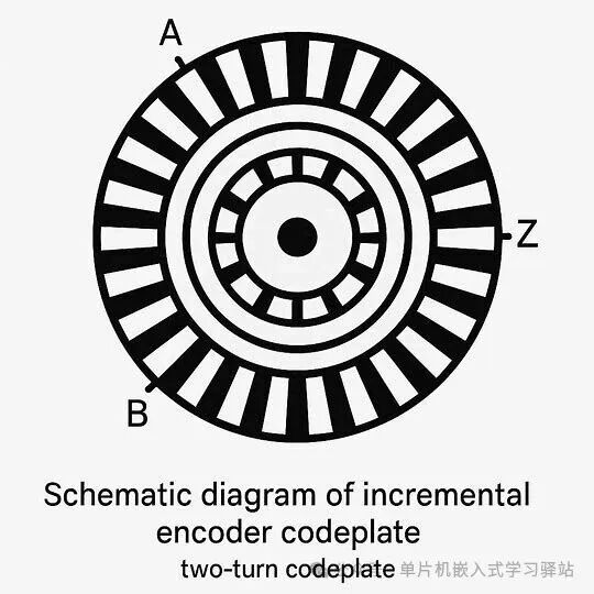
Code Disk Schematic
The electrical signal waveform output after detection is shown in the following figure:
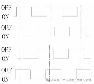
Counter-clockwise rotation waveform
The principle of absolute encoders is similar to that of incremental encoders, except that absolute encoders have more code disk circles, and each rotational position has a unique code;
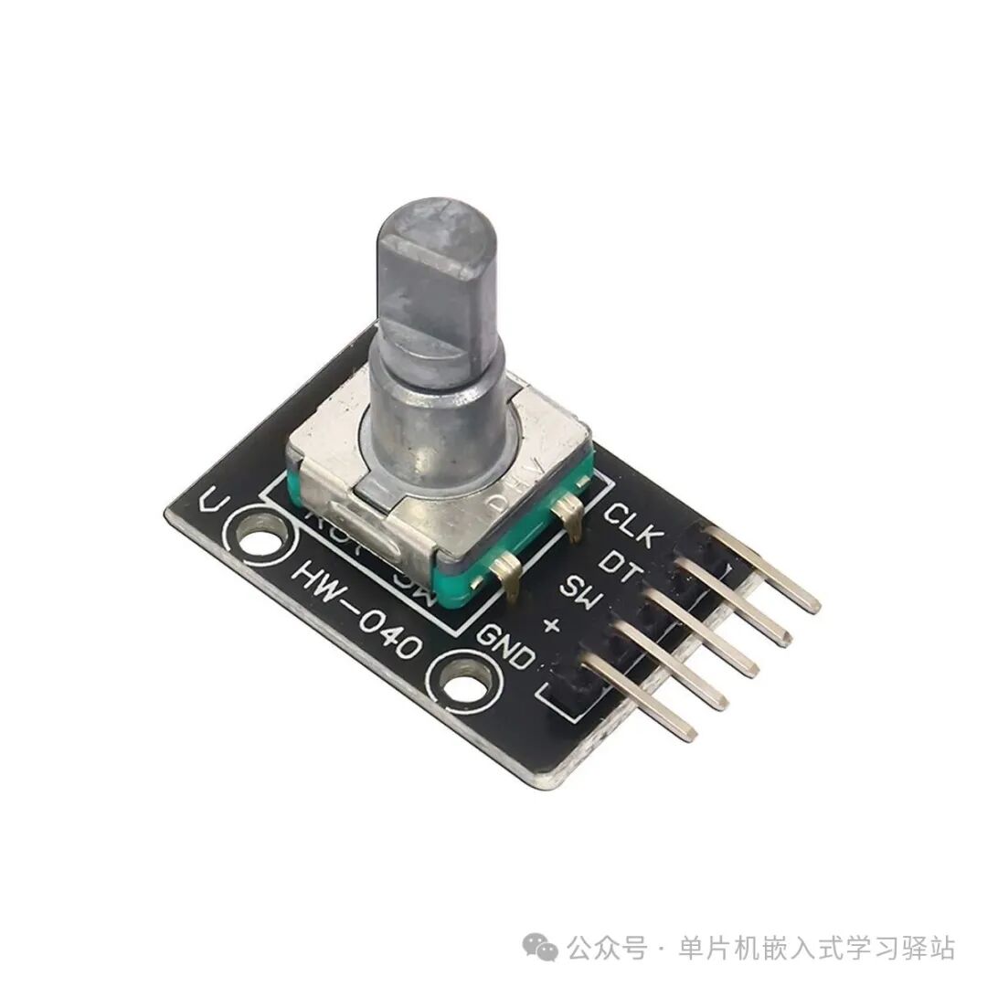
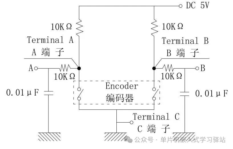
This article uses an incremental photoelectric encoder knob—EC11—to demonstrate the configuration and usage of the timer encoder interface;
Circuit Schematic:
02
—
Using Timer Encoder Interface Mode to Read Encoder
2.1 Introduction to Timer Encoder Interface Mode
In STM32 microcontrollers, only general-purpose timers and advanced timers have encoder interface modes; basic timers do not;
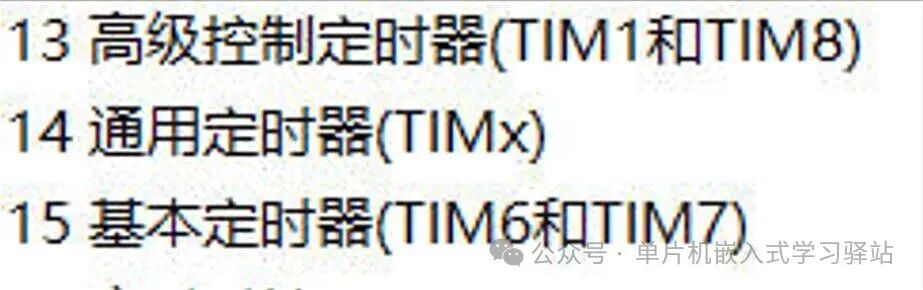
The timer’s encoder input interface generally only has channels 1 & 2, so be sure to find the corresponding input pins when wiring;
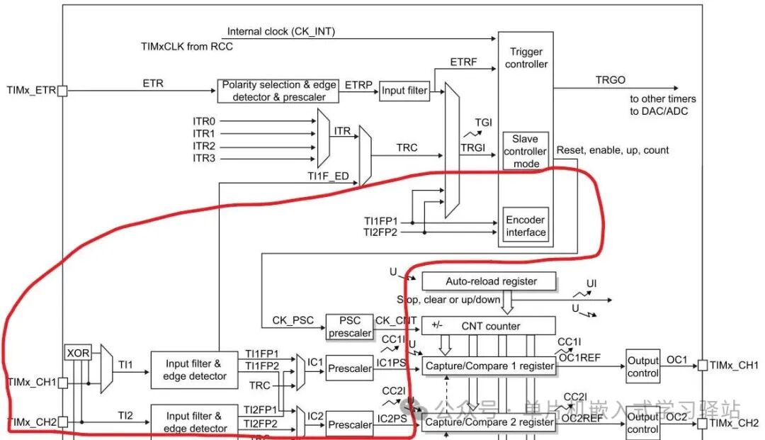
The STM32 timer encoder mode has the following counting modes:
-
Count only TI1;
-
Count only TI2;
-
Count TI1 & TI2 simultaneously;
The corresponding counting direction and signal transition relationship are shown in the table below:
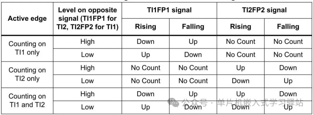
This table lists all possible counting methods corresponding to the interface configuration modes, but it may be difficult to understand. Here is a simple explanation:
TI1 and TI2 in the table correspond to the encoder’s A and B phase signals, TI1FP1 and TI2FP2 refer to the filtered and divided effective input signals of phases A and B, and the “Level on opposite signal” indicates the current sampling signal’s other signal level state (reference signal); the STM32 timer will integrate the signal conditions of both channels when counting pulses, with specific details as follows:
When configured for Counting on TI1 only:
-
If the reference signal is high, when TI1FP1 is at a rising edge, it counts down; if at a falling edge, it counts up;
-
If the reference signal is low, when TI1FP1 is at a rising edge, it counts up; if at a falling edge, it counts down;
This is the meaning of the table; other modes follow similarly;
2.2 Related Structure Definitions
To configure the timer for encoder interface mode, two configuration structures are involved (commonly using the register library for direct access):
“LL_TIM_InitTypeDef”: Configures the timer’s counting base and basic mode;
“LL_TIM_ENCODER_InitTypeDef”: Configures the encoder counting mode;
2.2.1 LL_TIM_InitTypeDef
First, the timer base needs to be configured, as it counts input pulses, so only the value for the reload counter needs to be set (i.e., the counting endpoint);
/** * @brief TIM Time Base configuration structure definition. */typedef struct{ uint16_t Prescaler;//Timer counting clock prescaler uint32_t CounterMode;//Counting direction uint32_t Autoreload;//Counting value uint32_t ClockDivision;//Counting input clock division } LL_TIM_InitTypeDef;2.2.2 LL_TIM_ENCODER_InitTypeDef
The encoder initialization configuration structureLL_TIM_ENCODER_InitTypeDef is used to configure the timer encoder interface mode, in conjunction with the LL_TIM_ENCODER_Init function to complete the encoder interface mode configuration;
typedef struct{ uint32_t EncoderMode; //Encoder interface mode uint32_t IC1Polarity; //Channel 1 polarity uint32_t IC1ActiveInput; //Channel 1 effective input uint32_t IC1Prescaler; //Channel 1 prescaler uint32_t IC1Filter; //Channel 1 filter uint32_t IC2Polarity; uint32_t IC2ActiveInput; uint32_t IC2Prescaler; uint32_t IC2Filter;}LL_TIM_ENCODER_InitTypeDef;-
EncoderMode: Encoder counting mode selection. Used to configure how the timer counts the encoder, can be set to count only channel 1, only channel 2, or both channels 1 & 2 simultaneously;
-
ICxPolarity: Input signal polarity selection, used to set the effective level of the input signal on the timer channel in encoder mode;
-
ICxActiveInput: Used to select the signal source for this channel, can choose channel 1, channel 2, or TRC signal;
-
ICxPrescaler: Prescaler for the input channel;
-
ICxFilter: Filter settings for the input channel, oversampling value, can choose between 0x0 to 0xf;
2.4 Actual Coding
Define a timer encoder mode initialization function “tim_encoder_if_init”:
First, configure the timer channel’s IO as a multiplexed input; then configure the timer, first setting the timer’s basic time base: counting endpoint as cnt, then configure the timer encoder mode: no prescaling or filtering of input signals, performing 4x frequency mode dual-channel counting;
The actual code is as follows:
//Timer encoder mode initializationvoid tim_encoder_if_init(TIM_TypeDef* pTim,uint16_t cnt){ //Enable the corresponding IO clock and timer clock __HAL_RCC_TIM3_CLK_ENABLE(); __HAL_RCC_GPIOA_CLK_ENABLE(); //Configure the corresponding IO as multiplexed input mode if(pTim == TIM3){ LL_GPIO_InitTypeDef cIO; cIO.Mode = LL_GPIO_MODE_ALTERNATE; cIO.Pull = LL_GPIO_PULL_UP; cIO.Pin = LL_GPIO_PIN_6|LL_GPIO_PIN_7; LL_GPIO_Init(GPIOA,&cIO); } //Configure the timer's basic time base LL_TIM_InitTypeDef cTim; LL_TIM_StructInit(&cTim); cTim.Autoreload = cnt; cTim.ClockDivision = LL_TIM_CLOCKDIVISION_DIV1; cTim.Prescaler = 0; cTim.RepetitionCounter = 0; LL_TIM_Init(pTim,&cTim); //Configure the encoder interface mode LL_TIM_ENCODER_InitTypeDef cTimEncode; LL_TIM_ENCODER_StructInit(&cTimEncode); cTimEncode.EncoderMode = LL_TIM_ENCODERMODE_X4_TI12; LL_TIM_ENCODER_Init(pTim,&cTimEncode); pTim->CNT = 0; //Enable the timer LL_TIM_EnableCounter(TIM3);}03
—
Actual Effect Testing
3.1 Test Code
In the main loop, periodically call to get the real-time counting value of the timer and read the timer counting direction bit, outputting test information via serial port;
uint16_t tim_get_encoder_val(TIM_TypeDef* pTim){ static uint16_t pre_val; uint16_t cur_val = pTim->CNT;//Get current counting value if(pre_val != cur_val){//Compare with the last counting value, if not equal execute if block uint32_t dir = (pTim->CR1&TIM_CR1_DIR)>>TIM_CR1_DIR_Pos; pre_val = cur_val; //Execute callback function LOG_INFO("dir:%s, encoder pos:%d\n",dir?"Decrease":"Increase",pre_val); } return pre_val;//Return counting value}In actual use, it can return the difference and counting direction, or directly execute a callback function passing the change amount;
3.2 Actual Testing Results
This concludes the content of this article. The next article will explain the output function of the timer—using PWM to implement a breathing light (temporarily using LED for demonstration as there is no motor), and combine it with the encoder knob from this article to achieve stepless dimming;
Thank you for reading. If you want to learn and communicate or obtain the source code project, you can join the QQ group. If this has helped you, please like and recommend it.




 。
。