Discussion on Liquid Level Detection Solutions
In order to accurately separate liquids with different components, it is essential to detect the position of the liquid level accurately. Only by quickly and accurately detecting the position of the liquid level can the separation of different components be completed precisely. There are generally three methods for detecting the position of the liquid level:1. Using sensors for measurement; 2. Measuring capacitance; 3. Detecting the liquid level through the different light transmittance of different solutions. Below is a brief discussion of the three methods mentioned above.The first method is to detect the position of the liquid level using sensors. Liquid sensors can detect liquids with different components and can reflect changes in the liquid through changes in voltage. Therefore, once the sensor detects the position of the liquid level, there will be a significant voltage change at the output of the sensor, and the position of the liquid level can be detected by judging this voltage signal through a voltage comparator.The main detection principle of the second method is based on the different conductivity of different solutions. Therefore, when the capacitive sensor is in different solutions, the capacitance value it detects will be different. When a change in capacitance value is detected, it indicates that the position of the liquid level has been detected.The detection principle of the third method mainly utilizes the different light transmission capabilities of liquids with different components, which means different light transmittance. By irradiating the liquid with an infrared light-emitting diode and receiving the infrared signal on the other side of the liquid, the received infrared signal is converted into an electrical signal. When the infrared light is irradiated on two different liquids, the strength of the signal received at the receiving end will be different, leading to different output voltage signals, thus accurately detecting changes in the liquid level.Among the three methods mentioned above, the main advantage of the first method is its simplicity and ease of maintenance, although its cost is higher compared to the third method; the second method is relatively complex and difficult to implement; the third method has a working principle similar to the first method and has the lowest cost among the three methods, but its main disadvantage is that there may be significant interference during detection, leading to poor detection results.
Discussion on Signal Processing Solutions:
After the front-end detection circuit completes the detection of the liquid level position, it is necessary to process the signal and make corresponding control actions. In the liquid level real-time detection and separation system designed this time, there are two processing methods: digital circuits andMCU.The first method uses digital circuits, where a voltage comparator compares the output voltage signal from the front-end detection circuit, and then controls the back-end execution circuit based on the output of the comparator.The second method uses a microcontroller as the core of the system’s detection and control. The microcontroller’s analog-to-digital converter collects and converts the output voltage from the front-end detection circuit, and then, through program algorithms within the microcontroller, determines the position of the liquid level and controls the subsequent execution circuit through the microcontroller’sIO.Both methods have distinct advantages and disadvantages. The first method’s advantage is its simple and clear circuit structure with high reliability; however, the disadvantage is that once the circuit design is finalized, subsequent upgrades and maintenance are relatively complex. The main advantage of the second method is that system functions can be improved by modifying the program, making it easy to upgrade and maintain; its main disadvantage is that the sampling microcontroller increases the complexity of the system, raising the risk of system failure.
Solution Determination:
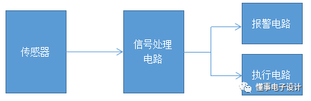
Through a detailed discussion of the liquid level detection and signal processing solutions, this design chooses the sensor+digital circuit method as the system structure for this design. The system structure block diagram is as follows:
Unit Circuit Design
Signal Processing Circuit Design:
The main function of the signal processing circuit is to process the liquid level signal detected by the front-end acquisition circuit and then drive the execution circuit to complete the separation operation. This design uses a voltage comparator as the core of the processing circuit, judging the voltage signal output from the front-end sensor to generate control signals that drive the control circuit to complete the liquid separation operation.
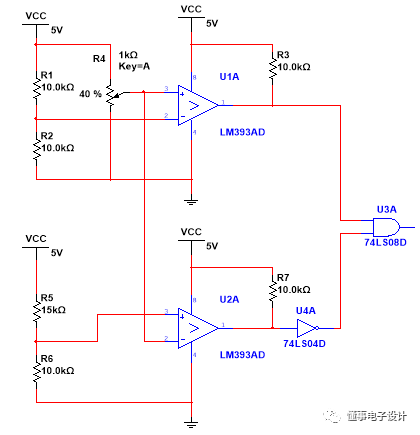
This design selects theLM393chip as the system comparator.LM393is a dual voltage comparator integrated circuit. The characteristics of this comparator chip are as follows:Wide operating power supply voltage range, can work with single or dual power supply, single power supply:2~36V, dual power supply:±1~±18V;Low current consumption,Icc=0.8mA;LM393has a small input offset voltage,VIO=±2mV;Wide common-mode input voltage range,Vic=0~Vcc-1.5V;Output compatible withTTL,DTL,MOS,CMOS, etc.;Output can be connected to an open-collector “or” gate;Available in dual in-line 8-pin plastic package (DIP8) and micro dual in-line 8-pin plastic package.
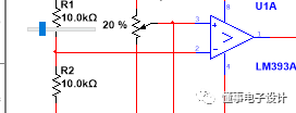
The application of the LM393 comparator is very simple, requiring only a few peripheral circuits to complete the comparator function.The following diagram shows the signal processing circuit designed this time. The signal processing circuit uses the two comparators inside the LM393 to form a dual comparator judgment circuit. When the input voltage is greater thanV1, the processing circuit outputs1; when the input voltage is less thanV0, the processing circuit outputs0; (V1>V0) thus forming a hysteresis loop to prevent frequent operations on the execution unit. The width of the hysteresis loop can be adjusted by changing the resistance values.
Sound and Light Alarm Circuit Design:
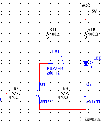
The following diagram shows the sound and light alarm circuit. The sound and light alarm circuit mainly utilizes the output of the signal processing circuit to achieve the sound and light alarm function. Since the output signal of the signal processing circuit uses74LS08, it cannot directly control the buzzer andLEDindicator light. Therefore, in this design, twoNPNtransistors are used to control the buzzer andLED. When the output of the signal processing circuit is high, indicating that the liquid level has been detected, the NPN transistor will conduct due to the high level applied by the base resistor, causing the buzzer to sound an alarm, while the LED will light up due to current flowing through it, thus achieving the sound and light alarm purpose.
Automatic Liquid Separation Circuit Design:
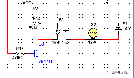
The following diagram shows the automatic liquid separation circuit. The automatic liquid separation circuit uses a relay to drive the solenoid valve. Once the signal processing circuit detects the liquid level signal, it will control the relay through the transistor, and the opening and closing of the relay will control the solenoid valve, thus achieving liquid separation.
Multisim Simulation
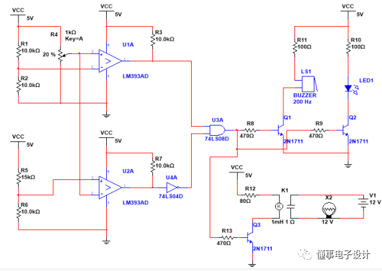
The circuit of the liquid level detection and separation system designed this time is shown in the figure. The composition of each part of the circuit has been introduced in previous chapters, and the next step is to introduce the simulation process. Click the run button at the top of the software.

The simulation has now started running. In the simulation circuit designed this time, a potentiometer is used to simulate the sensor, and by adjusting the output voltage of the potentiometer, the output of the sensor can be simulated.
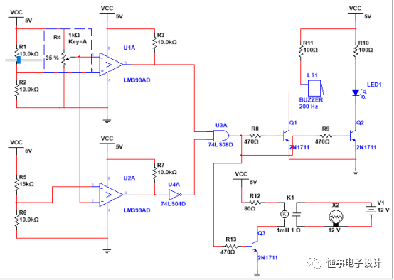
When we adjust the slider of the potentiometer to the right, the output voltage of the potentiometer gradually increases. When the voltage exceeds the set comparison voltage, we can see that the sound and light alarm device emits an alarm sound, and the relay operates, controlling the solenoid valve to complete the liquid separation operation. When we adjust the slider of the potentiometer to the left, the output voltage of the potentiometer gradually decreases. When it is less than the set voltage, the alarm contact is released, and the solenoid valve stops working.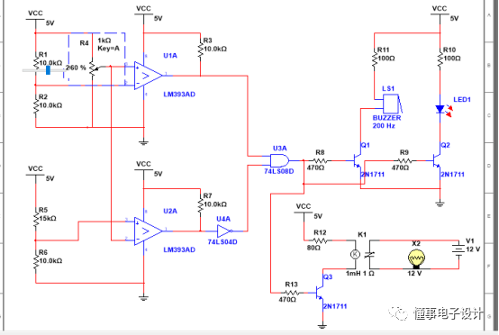
If you need the simulation source file, you can send “Multisim Simulation” in the public account interface.