Source: ittbank


Infrared Thermometer Technical Principles
All objects with a temperature above zero degrees (-273.15℃) continuously emit infrared energy into the surrounding space. The radiation characteristics, the amount of radiation energy, and the wavelength distribution are closely related to the surface temperature of the object. Conversely, by measuring the infrared energy radiated by the object itself, its surface temperature can be accurately determined. This is the mechanism of infrared radiation temperature measurement.
Like other biological entities, the human body also radiates infrared energy in all directions, with a wavelength generally between 9-13μm, which falls within the near-infrared band of 0.76-100μm. Since the light in this wavelength range is not absorbed by the air, the amount of infrared radiation emitted by the human body is independent of environmental influences and is only related to the amount of energy contained and released by the body. Therefore, by measuring the infrared energy radiated by the human body, the surface temperature can be accurately determined. The infrared temperature sensor for the human body is designed and manufactured based on this principle.
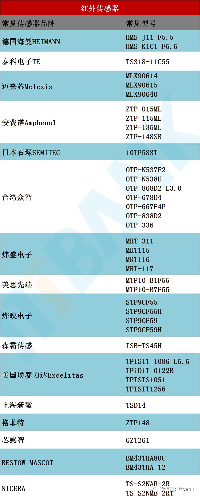
Infrared Temperature Sensors
Currently, the infrared temperature sensors available on the market can be categorized into several types based on the materials used for energy conversion:
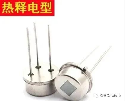
(1) Pyroelectric type: Triglyceride sulfate, lithium tantalate, etc.
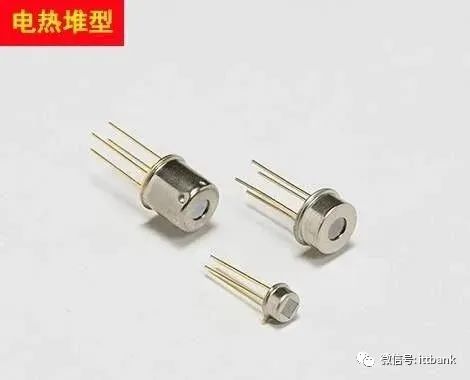
(2) Thermopile type: N-type and P-type polycrystalline silicon
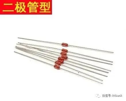
(3) Diode type: Monocrystalline or polycrystalline PN junction
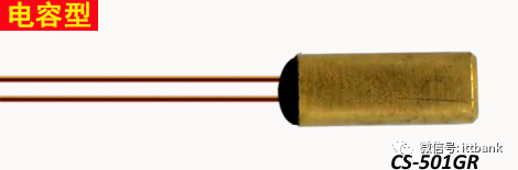
(4) Thermoelectric capacitor type: Bilayer thin film
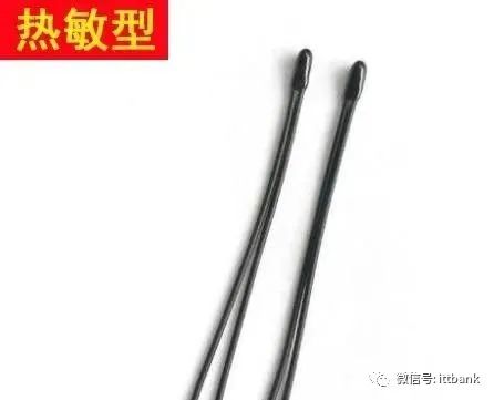
(5) Thermistor type: Vanadium oxide, amorphous silicon, etc. In fact, these types differ only in the way of receiving infrared energy and the efficiency of the conversion materials.

Currently, both ear and forehead thermometers use thermopile infrared sensors, and the basic physical principle is the Seebeck effect.
Parameters of thermopile temperature sensors:
Measurement range: -50℃-100℃;
Measurement accuracy: within 0.1℃, ±0.1%;
Operating temperature: -20℃-+85℃;
Maximum measurement distance: ≦0-50mm (with lens 300-500mm)
Output voltage: 0-10mV;
The maximum measurement range of thermopile temperature sensors can reach from -60℃ to +1200℃.
The main packaging forms of infrared thermopile sensor products are mainly two types: TO46(TO18)/TO39(TO5);
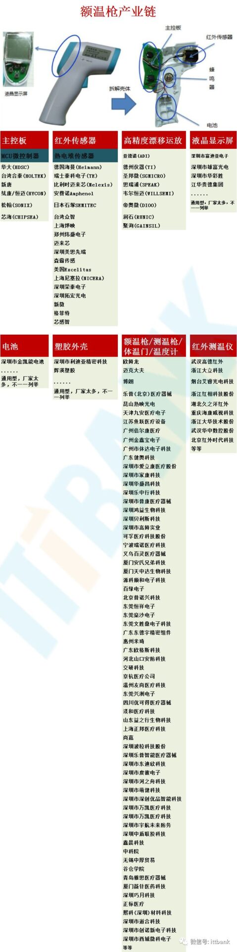
Infrared Thermometer Chip
The core chip of the infrared thermometer mainly consists of ADC chips and control chips, which can achieve key control, LCD display, battery detection, and other functions.
The working process of infrared thermometers: infrared thermometers consist of optical systems, photoelectric detectors, signal amplifiers, signal processing, and display output. The optical system gathers the infrared radiation energy of the target within its field of view, and the size of the field of view is determined by the optical parts and position of the thermometer. The infrared radiation emitted by the measured object first enters the thermometer’s optical system, where it is focused to concentrate the energy; the gathered infrared rays are then input into the photoelectric detector, where the key component is the infrared sensor, which converts the optical signal into an electrical signal; the electrical signal output from the photoelectric detector is amplified and processed by the signal processing circuit according to the internal algorithm and the target emissivity correction, transforming it into the temperature value of the measured target.
Calibration of Human Forehead Thermometers
Ambient temperature: Place the sensor in a water tank at 25.00 +/-0.02 degrees, wait for stabilization, and then press a button to confirm, which generally takes 30 seconds.
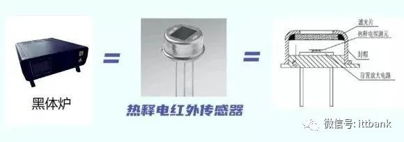
Black body temperature: First, adjust the black body furnace to 37.00 +/-0.02 degrees, then insert the sensor into the black body furnace, wait for stabilization, and press a button to confirm. This generally takes 20 seconds.
What is Needed for Scheme Design and Product Production
1. How many functional keys does the shell have, and what are their functions?
2. How many pins does the LCD screen need?
3. Is the sensor digital or analog?
4. Product specifications: what kind of battery is used, is it for home or medical use, does it need calibration?
Production Testing Requirements
2. Does the factory have a constant temperature room? Can it adjust to high, medium, and low temperatures?
3. Do you know how to deal with heat sinks? If one of the structure, optical components, or sensors has a problem, it leads to continuous testing and correction, which is also an unclear factor; electronic design engineers may not be able to solve these problems.
4. Do you have clinical trial resources? (Find hospitals; they have people with and without fever to collect data for a period of time)
5. If doing medical regulations, do you have domestic CFDA medical qualifications? The foreign equivalents are called FDA and CE Medical (CFDA takes at least a year and a half for approval).
Infrared Thermometer Design Scheme
Scheme Overview
Non-contact infrared thermometers are a new type of instrument that uses modern sensor measurement technology, microelectronics technology, and other technical means to measure the temperature of the measured object. When the infrared thermometer is aimed at and close to the measured object within the effective distance detected by the digital proximity sensor, pressing the power/measurement button and holding it for a few seconds will allow the internal infrared sensor module of the thermometer to collect the temperature, converting it into an electrical signal, which is then converted into a digital signal and transmitted to the microcontroller through a communication interface. The microcontroller collects the current ambient temperature through the digital temperature sensor and performs corresponding temperature compensation on the transmitted temperature digital signal, storing the corrected temperature as the current record number, while determining the LCD backlight range for corresponding backlight display: (35.0-37.4℃) normal body temperature green backlight, (37.5-37.9℃) elevated body temperature yellow backlight, (38-42.9℃) high body temperature red backlight; if the body temperature is abnormal, it will also emit a “beep” alarm, and finally announce the current temperature. If not used for more than 30 seconds, it will automatically enter low power mode to save energy.
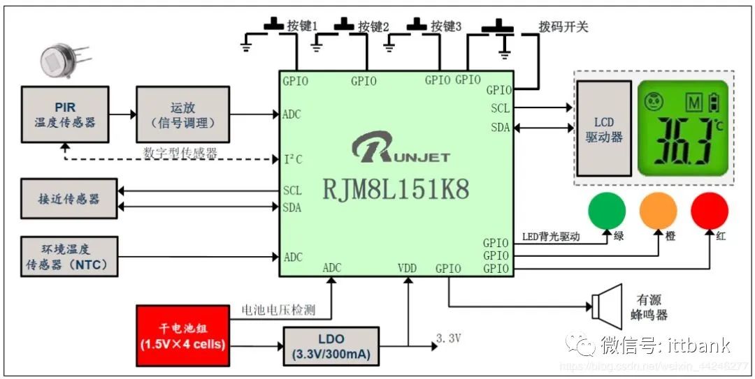
Hardware Block Diagram of the Scheme
This non-contact infrared thermometer scheme consists of ultra-low power, high safety MCU: RJM8L151, power module, button module, infrared sensor module, temperature sensor (module), digital proximity sensor module, ambient temperature sensor, voice module, speaker, and LCD display module. The hardware block diagram is as follows:
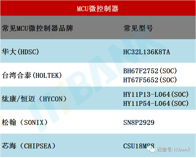
1. Microcontroller MCU
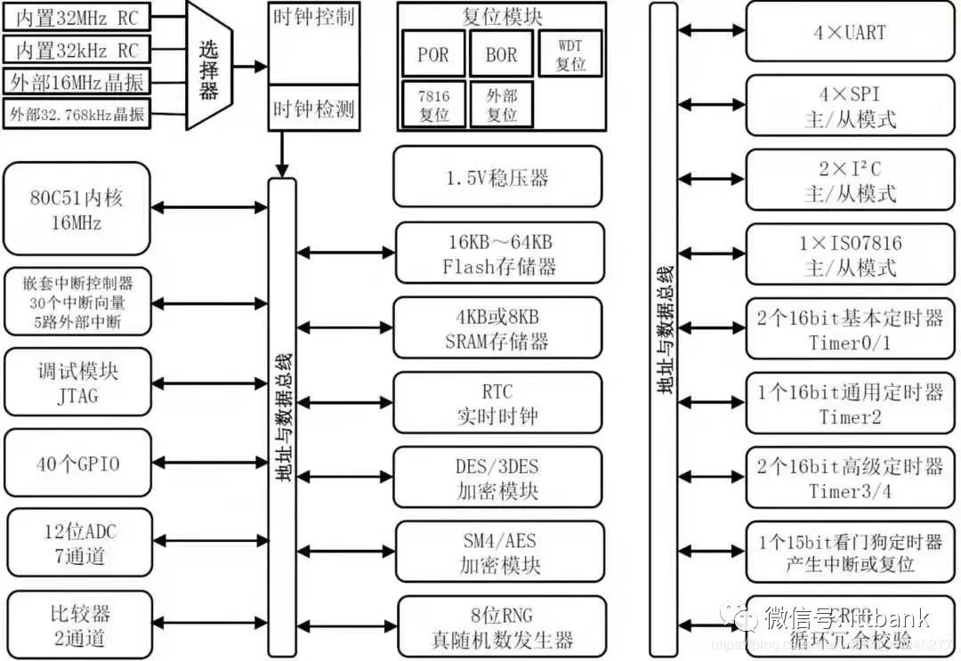
The ultra-low power, high safety RJM8L151 series MCU launched by Wuhan Ruina Technology Co., Ltd. is used. This chip has excellent operating and standby power consumption performance, supporting 4-channel IO wake-up of the chip. It integrates a 12-bit high-precision successive approximation ADC, a 2-channel multifunction comparator, a timer, a real-time clock (RTC), a watchdog timer (WDT), programmable voltage detection (PVD), an interrupt controller, a hardware true random number generator, an AES/DES/SM4 hardware encryption engine, and communication interfaces: UATR, SPI, IIC, GPIO, ISO7816, JTAG, etc. The chip is characterized by high cost-performance, large storage capacity, high security, low power consumption, and rich interfaces. The hardware block diagram of the RJM8L151 series safety MCU is shown below:
2. Power Module
Powered by 2 AAA batteries, the power module maintains the output voltage using a voltage conversion chip to ensure that the MCU, infrared sensor, digital proximity sensor, voice chip, LCD screen, and other modules operate normally and stably even when the battery voltage decreases.
3. Sensor Module
A) An integrated infrared sensing module is used, which includes an infrared thermopile sensor and a dedicated processing chip. The advantages are stable circuits, simple interfaces, and easy debugging, while the disadvantage is the high cost. Sensor signals can use MLX90614, HMS K1C1 F5.5, and 10TP583T, among others, as shown below:
The infrared sensor MLX90614’s infrared sensing part is an 81101 thermoelectric unit, which receives the infrared radiation signal from the target object and then amplifies and processes the signal through the internal DSP signal processing dedicated integrated chip MLX90302 and 17-bit ADC. The measurement accuracy can reach 0.2%, with fast measurement speed and low power consumption. The MLX90614 supports sleep mode. The digital temperature sensor is mainly used to measure the ambient temperature for infrared sensor temperature compensation to enhance accuracy, and the digital proximity sensor is used to detect the effective distance during measurement.
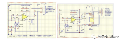
B) Using a thermopile sensor + peripheral circuit, the advantage is lower cost, while the disadvantage is that the small signal amplification and processing circuit and temperature compensation circuit need careful design and debugging, resulting in a longer product design cycle. Sensor signals can use MTP10-B7F55, RTP678, etc., as shown below:
Using Sunny’s MTP10-B7F55 can achieve fast, high-precision temperature measurement. It has an internal NTC that can measure ambient temperature for temperature compensation to enhance accuracy, and its application methods can be flexibly chosen, as follows:
(a) Software temperature compensation (b) Hardware temperature compensation
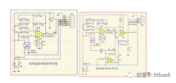
(c) Analog interface (d) Digital interface
3.2 Digital Proximity Sensor
Used to determine the distance between the measured object and the PIR sensor; measurement is only initiated under the optimal distance ratio to ensure the accuracy of measurement data, for example, TMD26721.
3.3 Ambient Temperature Sensor
The role is to obtain the ambient temperature during measurement, so as to exclude the ambient temperature from the measurement value of the infrared temperature sensor, deriving the measured human body temperature, and compensating the infrared temperature sensor. Some ambient temperature sensors are integrated into the thermopile sensor, such as MTP10-B7F55.
4. Button Module
The design includes 5 independent buttons: power/measurement button, SET button, UP button, DOWN button, and MODE button, with the first four buttons having sleep wake-up functionality.
Power/Measurement Button: Press the button to wake up from sleep and execute a temperature measurement, displaying the current temperature upon completion.
SET Button: Press the button to wake up from sleep and enter the function setting mode; pressing it once corresponds to the following functions:
F1 Display unit switch: default is °C, pressing the UP button switches to °F, pressing the DOWN button switches back to °C.
F2 Voice broadcast switch ON/OFF: default is ON, pressing the UP button switches to ON, pressing the DOWN button switches to OFF.
F3 Delete temperature records.
UP Button: Scrolls up through the current temperature records until reaching record 32, then loops back to record 1.
DOWN Button: Scrolls down through the current temperature records until reaching record 1, then loops back to record 32.
MODE Button: Switches between human/body surface modes.
5. Voice Module
Using voice chips WTN1010/VC505 to store voice segments, such as ‘ten’, ‘℃’, ‘℉’, ‘one’, ‘two’, …, ‘nine’, ‘beep’, etc., playing selected segments to form complete speech, driving the speaker to sound.
6. LCD Display Module
Using RFD-TA20001ZT-11 to display current temperature, current memory temperature, measurement mode, battery status, voice switch status, and other information.
Scheme Functional Specifications
2) Measurement distance: 3~8CM.
3) Measurement modes: Human mode: 32.0-42.9℃ (89.6-109.3°F)
Body surface mode: 0.0-99.9℃ (32.0-211.9°F)
4) Measurement time: < 6s
5) Measurement accuracy: ±0.2℃ (35.0°-42.0℃); ±0.3℃ (other ranges)
6) Display resolution: 0.1°C or 0.1°F
7) Display units: °C (Celsius) and °F (Fahrenheit)
8) Supports 32 groups of memory storage
9) Supports three-color backlight display
Normal body temperature green backlight (35.0-37.4℃)
Elevated body temperature yellow backlight (37.5-37.9℃)
High body temperature red backlight (38-42.9℃)
10) Supports low battery display
11) Supports voice broadcast
12) Supports automatic shutdown to save energy.
The advantages of RJM8L151:
1) Ultra-low power consumption
Up to 6 low-power management modes are available, with deep sleep power consumption at 5nA, external wake-up less than 5us, and supporting 4-channel IO wake-up. The Halt mode has power consumption as low as 0.4uA while retaining RAM data, significantly extending battery life.
2) Built-in PVD programmable voltage detection
Can perform rapid staged detection and management of the input voltage after battery boosting.
3) Built-in 12-bit high-precision successive approximation ADC
Can directly perform real-time, accurate voltage acquisition of the battery for digital display and monitoring of battery usage status.
4) Rich communication interfaces
The chip supports UATR, SPI, IIC, GPIO, ISO7816, etc., providing more communication options for peripheral devices to expand functionality.
5) 15-bit watchdog timer
Includes a 1-channel 15-bit watchdog timer that can reset the system in case of abnormal operation or system freeze, returning the system to normal operation, further enhancing stability.
6) Secure memory
High-strength physical protection circuits are designed for internal Flash, SRAM, and other storage units to effectively prevent malicious code theft and reverse analysis.
Copyright statement:This scheme is an original article by CSDN blogger “1028_Yang”, following the CC 4.0 BY-SA copyright agreement. Please attach the original source link and this statement when reprinting.
Original link:https://blog.csdn.net/weixin_44246277/article/details/104365045
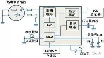
Digital Circuit Technology of Ear Thermometers
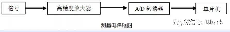
The principle of digital processing is to convert the signals from thermistors and thermopiles into electrical signals, amplify them, and collect data via A/D conversion by the microcontroller to obtain the corresponding temperature value.
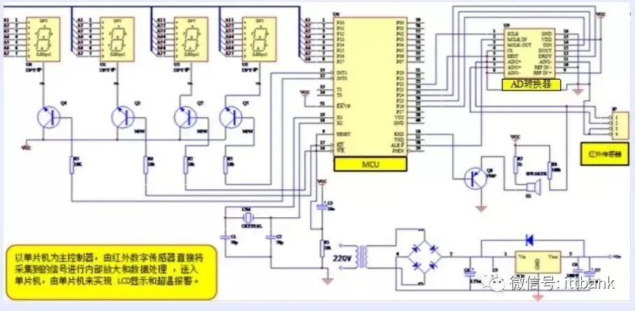
Complete circuit system
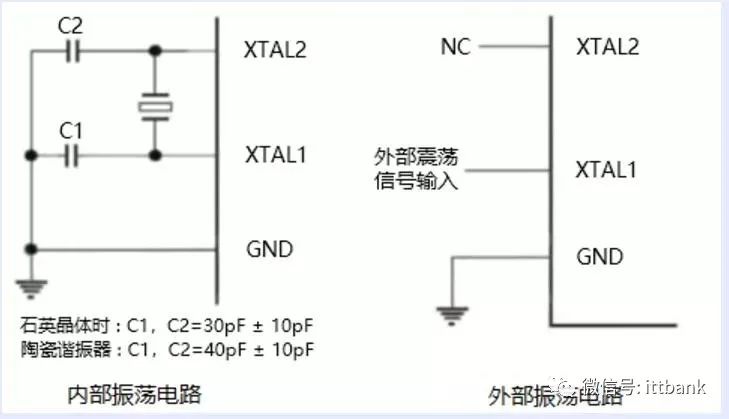
2. Clock circuit
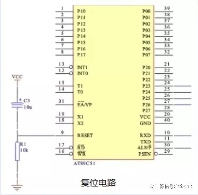
3. Reset circuit
———— / END / ————
Note:If there are any omissions or errors, please correct them. Contact information is as follows:
Submission Email: [email protected]
ITTBANK Customer Service Hotline: 25839333
Statement: Please indicate the source when reprinting!