What are the different air packet formats in BLE? What are the common PDU commands? What is the difference between PDU and MTU? What is DLE? How does BLE implement retransmission? What is the principle of the BLE ACK mechanism? I hope this article can help answer these questions.
Although the BLE air packet (also known as air interface packet) involves various layers of the BLE protocol stack including link layer, L2CAP, SMP, and ATT, the link layer is most closely related to the air packet format. Once you grasp the format of the BLE packet, understanding the working principle of the BLE link layer protocol becomes much easier. Therefore, the article is titled “Detailed Explanation of BLE Air Packet Format and Link Layer Protocol Analysis.”
BLE Packet Format
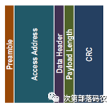
The BLE link layer defines only one type of packet (air packet), as shown below:
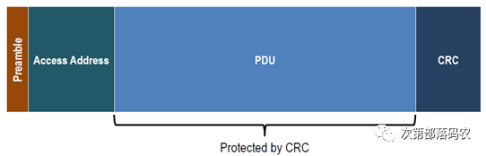
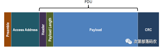
Moreover, the first two bytes of the PDU (protocol data unit) are fixed as LL header (1 byte long) and payload length (1 byte long, also known as data length), which means the above Packet can be expanded as follows:
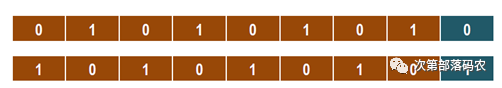
preamble (Leading Frame) is 1 byte and has two possible values based on the first Bit of the Access Address: 0x55 or 0xAA (pure PHY layer behavior), as shown below:
Access Address is used to indicate the receiver ID or the identity of the air packet. As mentioned earlier, BLE has only one packet format, and based on different Access Addresses, it distinguishes between two types of packets: broadcast packets and data packets:
-
Broadcast Packet Access Address is fixed at 0x8E89BED6, and broadcast packets can only be transmitted on broadcast channels (channel), specifically on 37/38/39 channels (Note: Starting from Bluetooth 5.0, broadcast packets can be transmitted on other channels). Broadcast packets are sent to all nearby observers (scanners).
-
Data Packet Access Address is a 32-bit random value generated by the Initiator. The data packet is actually an abbreviation for air packets on the data channel, and data packets are only transmitted on data channels, specifically on the remaining 37 channels (excluding 37/38/39, as BLE occupies a total of 40 channels). Each time a connection is established, a new Access Address is generated. Data packets are used for connection communication, specifically for communication between master and slave.
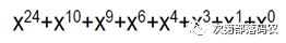
CRC is 24 bits, with the initial vector as:
Bluetooth Broadcast Packet
The Bluetooth broadcast packet, formally known as the Bluetooth broadcast channel air packet, is a type of air packet transmitted on the Bluetooth broadcast channel, with the specific format shown below:
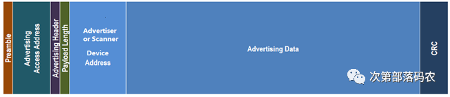
Advertising Header refers to the aforementioned LL header, with a length of one byte, and each bit is defined as follows:

-
PDU Type is 3 bits, with specific definitions as shown. It can be seen that Scan PDU and Connection Initiation PDU both belong to broadcast packets.
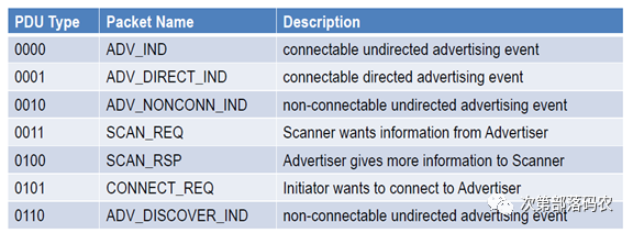
Note: CONNECT_REQ can also be written as CONNECT_IND
-
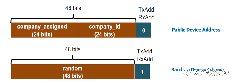
TxAdd/RxAdd, each occupying 1 bit, indicates the type of Bluetooth MAC address represented by the subsequent Device Address field, where value 0 represents Public address and value 1 represents Random address.
Payload length is defined as follows, so the maximum length of the broadcast packet PDU is 37 bytes.

Device Address is a mandatory field in the broadcast packet, commonly known as Bluetooth MAC address. If it is a broadcast packet, it represents the advertiser’s MAC address; if it is a scan packet or connection request packet, it represents the scanner’s MAC address. The Bluetooth device address is 6 bytes, which means the maximum Advertising data length is: 37-6 = 31B, and this is why the broadcast packet data can only be a maximum of 31 bytes. As mentioned earlier, the device address can be public or random, defined as follows:
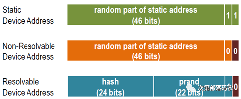
Random device addresses can have three types, defined as follows:
Advertising data will be detailed in another article, so I will not introduce it here.
Below is a complete example of a real broadcast packet. Note: BLE air packets use little-endian format.
-
AAD6BE898E600E3B75AB2A02E102010504FF5900538EC7B2
-
AA – Leading Frame (preamble)
-
D6BE898E – Access Address
-
60 – LL Frame Header Field (LL header)
-
0E – Valid Data Packet Length (payload length)
-
3B75AB2A02E1 – Advertiser Device Address
-
02010504FF590053 – Broadcast Data
-
8EC7B2 – CRC24 Value
Note: The above broadcast packet is in Bluetooth 4.x format. The Bluetooth 5.0 broadcast packet, in addition to the above format (remember: Bluetooth 5 is compatible with Bluetooth 4.x!), also has some new definitions. I will also write an article specifically discussing the extended broadcast packets of Bluetooth 5.
Bluetooth Data Channel Air Packet (Data Packet)
Corresponding to the Bluetooth broadcast packet, the Bluetooth data packet is another type of BLE packet. The Bluetooth data packet is an abbreviation for air packets on the Bluetooth data channel, meaning that the air packet is transmitted only on the Bluetooth data channel, specifically on the other 37 channels (excluding 37/38/39). In terms of format, the Bluetooth data packet can be divided into empty packets and ordinary data packets, with the empty packet format shown below.
As seen from the diagram, the entire payload of the empty packet is empty, hence the name empty packet.
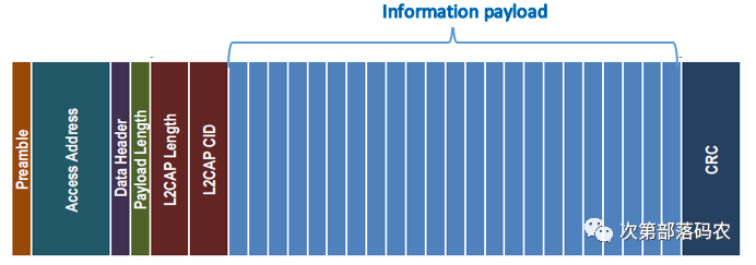
The ordinary data packet format is shown below:
Data header, which is the aforementioned LL header, is defined in the data packet as follows:

-
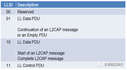
LLID (2 bits), link layer ID, classifies LL PDU into: LL data PDU and LL control PDU. This means that ordinary data channel air packets include both LL data packets and LL control packets, with specific definitions as shown. Please pay attention to distinguishing between data channel packet (data channel air packet) and LL data packet (LL data packet); as mentioned earlier, data channel packet includes LL data packet and LL control packet, and LL data packet is just one type of data channel packet. When there is no contextual ambiguity, we refer to them collectively as “data packets”.
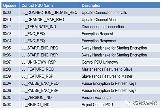
LL Control PDU interacts directly at the Link layer, meaning they do not pass through the subsequent L2CAP layer. The Link layer supports the following control PDUs:
-
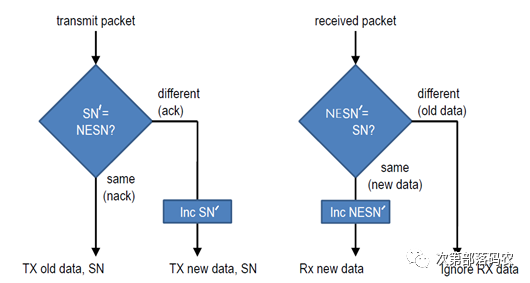
NESN/SN, each occupying 1 bit. SN stands for sequence number, indicating the current packet number being sent. NESN, next expected sequence number, informs the other party of the next expected packet number. The Link layer uses SN to inform the other party whether this packet is a new data packet or a retransmission packet, and uses NESN to inform the other party that the previously sent packet has been received (serving the role of ACK). Please refer to the following table to carefully consider how NESN and SN are encoded to simultaneously achieve the functions of ACK and retransmission.
|
Air Packet Number |
Transmission Direction |
NESN |
SN |
NESNꞌ |
SNꞌ |
|
#1 |
M -> S |
1 |
0 |
||
|
#2 |
S -> M |
1 |
1 |
||
|
#3 |
M -> S |
0 |
1 |
1 |
0 |
|
#4 |
S -> M |
0 |
0 |
1 |
1 |
Let’s analyze data packet #3, which is sent from master to slave. How are the NESN and SN for #3 determined? In fact, the NESN and SN for #3 are determined by comparing the NESN/SN values of #1 and #2. After the master sends #1, it records the NESN and SN of #1, which are shown in the right-side NESNꞌ and SNꞌ. The master will then compare SNꞌ with the NESN of #2. If they are not equal, it indicates that the slave has received packet #1 and expects a new packet from the master. At this point, the master increments SNꞌ by 1 to form the SN for #3, indicating that this data packet is a new packet, and sends it out. If they are equal, it indicates that the slave has not received packet #1, and the master needs to retransmit. The master also compares NESNꞌ with SN of #2; if they are equal, it indicates that packet #2 is a new packet, and the master increments NESNꞌ by 1 to form the NESN for #3, informing the slave that it has received packet #2 and is expecting the next packet from it; if they are not equal, it indicates that packet #2 is a retransmission packet. Note: You can observe a pattern from the above table; that is, for two adjacent data packets in the same direction, their NESN and SN values are opposite to those of another packet. For example, #3 NESN = #1 NESN, #3 SN = #1 SN, and similarly, #2 and #4 have their NESN and SN values being mutually opposite.
We can use the following flowchart to describe the above process.
-
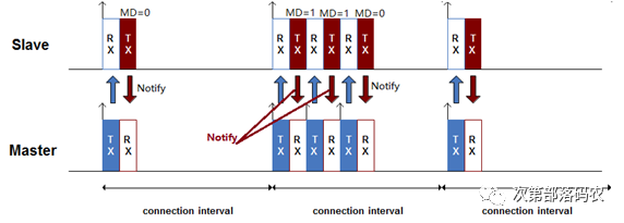
MD (1 bit), more data, indicates to the other party that there are more data packets to be transmitted, and asks them to continue opening the RF window to prepare for reception. For example, a Nordic nRF51822 can send 6 packets or more in one connection interval (meaning one connection event includes multiple data packet interactions), which is achieved using MD. Taking the notify command as an example, the device (Server) notifies the first data packet and sets MD to 1. The client (e.g., mobile phone) receives this notify command and knows that the server has more data packets to transmit. At this point, the mobile phone can continue to send an empty packet to the device to allow the device to send the second notify command. The details are as follows. Note: The master is the mobile phone (Client), and the slave is the device (Server).
Payload Length or Data Length, defined as follows for BT4.0/4.1, is the root cause of why a Bluetooth 4.0/4.1 packet can only transmit 20 bytes.

After BT4.2, the Payload length uses all 8 bits to represent length, allowing the maximum payload size to reach 251 bytes (255 – MIC size). After establishing a BLE connection, the data length can be dynamically changed (default is 27 bytes), a feature called Data Length Extension (DLE), which is implemented through Link layer commands: LL_LENGTH_REQ and LL_LENGTH_RSP. The data length is directly related to the RF capability of the Bluetooth chip. For example, the Nordic nRF51822 only supports BT4.1’s data length because the PHY layer is fixed and cannot be extended, but Nordic’s latest nRF52832 and nRF52840 support DLE, allowing the data length to reach a maximum of 251 bytes.
L2CAP length, 2 bytes in length, indicates the length of the subsequent information payload. The maximum length of the information payload is constrained not only by this L2CAP length field but also by MTU limits. MTU, Maximum Transmission Unit, is the maximum data length that can be exchanged between the ATT layer and the L2CAP layer, or the maximum length that can be exchanged between the Client and Server.
To summarize, the Bluetooth specification defines two length fields: LL data length and L2CAP length, while the ATT layer also defines an MTU to limit the maximum length of ATT PDU. LL data length can be dynamically changed through LL_LENGTH_REQ and LL_LENGTH_RSP, while the MTU size can be changed through the Exchange MTU Request and Exchange MTU Response that will be discussed later. The L2CAP length cannot be changed dynamically, meaning it cannot exceed 65535.
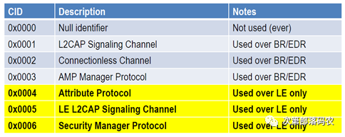
L2CAP CID, 2 bytes in length, is the ID of the logical channel. BLE uses fixed channel numbers. Although the Bluetooth specification also allows BLE to use connection-oriented channels, most BLE protocol stack implementations use fixed channel numbers. The channel numbers are defined as follows:
BLE L2CAP Signaling Channel supports only three PDU commands:
-
Command reject
-
Connection parameter update request, to update connection parameters such as minimum connection interval, maximum connection interval, slave latency, etc.
-
Connection parameter update response, to accept or reject the above request.
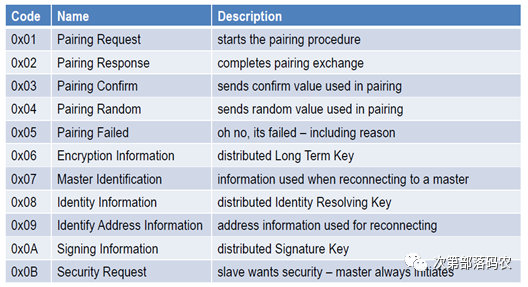
Security Manager Protocol (SMP) is used for pairing and key distribution. SMP supports the following PDU commands:
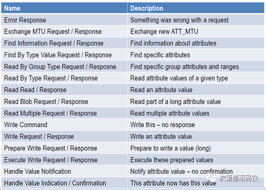
Attribute Protocol (ATT) is the application layer we often use, and application data follows the ATT commands. ATT supports the following command list:
Thus, the analysis of BLE air packets concludes here. Beyond this point is the analysis of application layer data, which is outside the scope of air packets and is defined by GATT and profile. Students interested in GATT/ATT/Profile can refer to: Interpretation of Low Power Bluetooth ATT/GATT/Profile/Service/Characteristic Specifications.
Below is a complete example of a real data packet. Note: BLE air packets use little-endian format.

-
AAAB5D65501E08040004001B130053D550F6
-
AA – Leading Frame (preamble)
-
0x50655DAB – Access Address
-
1E – LL Frame Header Field (LL header)
-
08 – Valid Data Packet Length (payload length)
-
04000400 – ATT Data Length and L2CAP Channel Number
-
1B – Notify Command
-
0x0013 – Application Data Handle
-
0x53 – Actual Application Data
-
0xF650D5 – CRC24 Value