The digital-to-analog (DAC) and analog-to-digital (ADC) conversion in microcontrollers is a key technology that connects digital systems with the analog world.
1. Basic Concepts
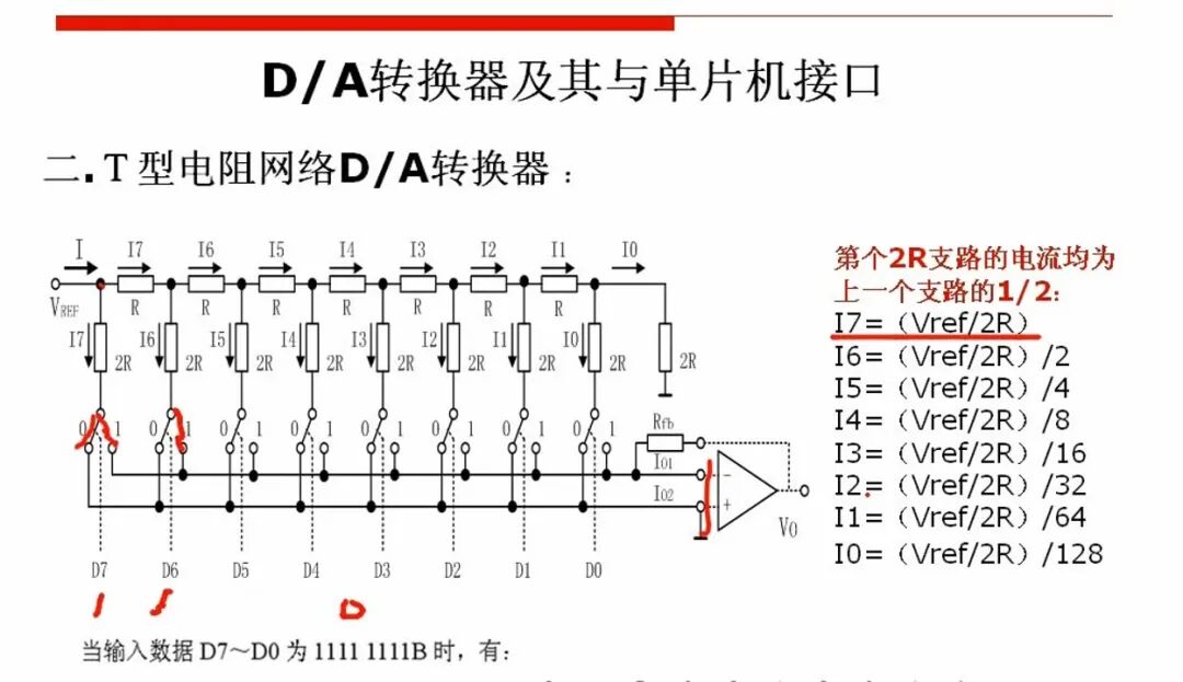
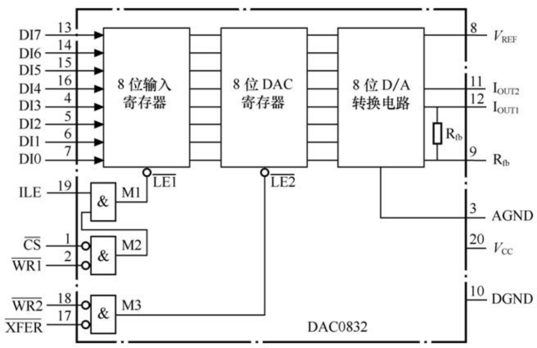
1. DAC (Digital-to-Analog Converter)
Function: Converts digital signals into analog signals (such as voltage or current).
Application Scenarios: Driving motors, audio output, LED dimming, etc.
Implementation Methods: Weighted resistor networks, R-2R ladder networks, PWM analog (requires low-pass filter).
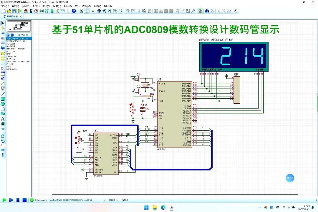
2. ADC (Analog-to-Digital Converter)
Function: Converts analog signals (such as sensor data) into digital signals for processing by the microcontroller.
Application Scenarios: Temperature detection, light intensity measurement, sound acquisition, etc.
Implementation Methods: Successive approximation (SAR), dual-slope, parallel comparison (Flash ADC).
2. Key Parameters
1. Resolution
Definition: The precision of conversion, expressed in bits (e.g., 8-bit, 12-bit).
2. Conversion Rate
ADC: Determines the sampling frequency (e.g., 100 kSPS).
DAC: Affects the upper limit of output signal frequency (e.g., high-speed DAC is required to generate high-frequency waveforms).
3. Reference Voltage
Determines the conversion range and must be stable (e.g., internal reference or external precision reference source).
3. Hardware and Configuration
1. Integrated Modules
Some microcontrollers have built-in DAC/ADC (e.g., STM32’s 12-bit ADC, Arduino’s 10-bit ADC).
If there are no built-in modules, external chips are required (e.g., ADS1115 ADC, MCP4725 DAC).
2. Register Configuration
ADC: Set channel, reference voltage, sampling time, trigger mode (e.g., polling or interrupt).
DAC: Configure output mode (e.g., direct or buffered), data alignment.
4. Application Practice
1. ADC Sampling Example
Steps: Initialize ADC → Select channel → Start conversion → Read result.
Filtering: Hardware RC filtering or software filtering (moving average, Kalman filtering).
2. DAC Output Example
Direct Output: Write digital value to DAC register, output corresponding voltage.
PWM Simulated DAC: Adjust duty cycle and smooth through a low-pass filter.
5. Common Issues and Solutions
1. Noise Interference
Use shielded cables, add decoupling capacitors, shorten trace distances.
Software uses digital filtering algorithms (e.g., median filtering).
2. Calibration and Errors
Zero Calibration: Eliminate offset errors (e.g., ADC output at zero input).
Gain Calibration: Adjust slope to ensure full-scale accuracy.
6. Extended Knowledge
Differential Input: Measures the voltage difference between two pins, suppressing common-mode noise (e.g., sensor bridge).
Bipolar DAC: Outputs positive and negative voltages (e.g., ±5V), requires external operational amplifier circuit.
7. Experimental Suggestions
1. Basic Experiments
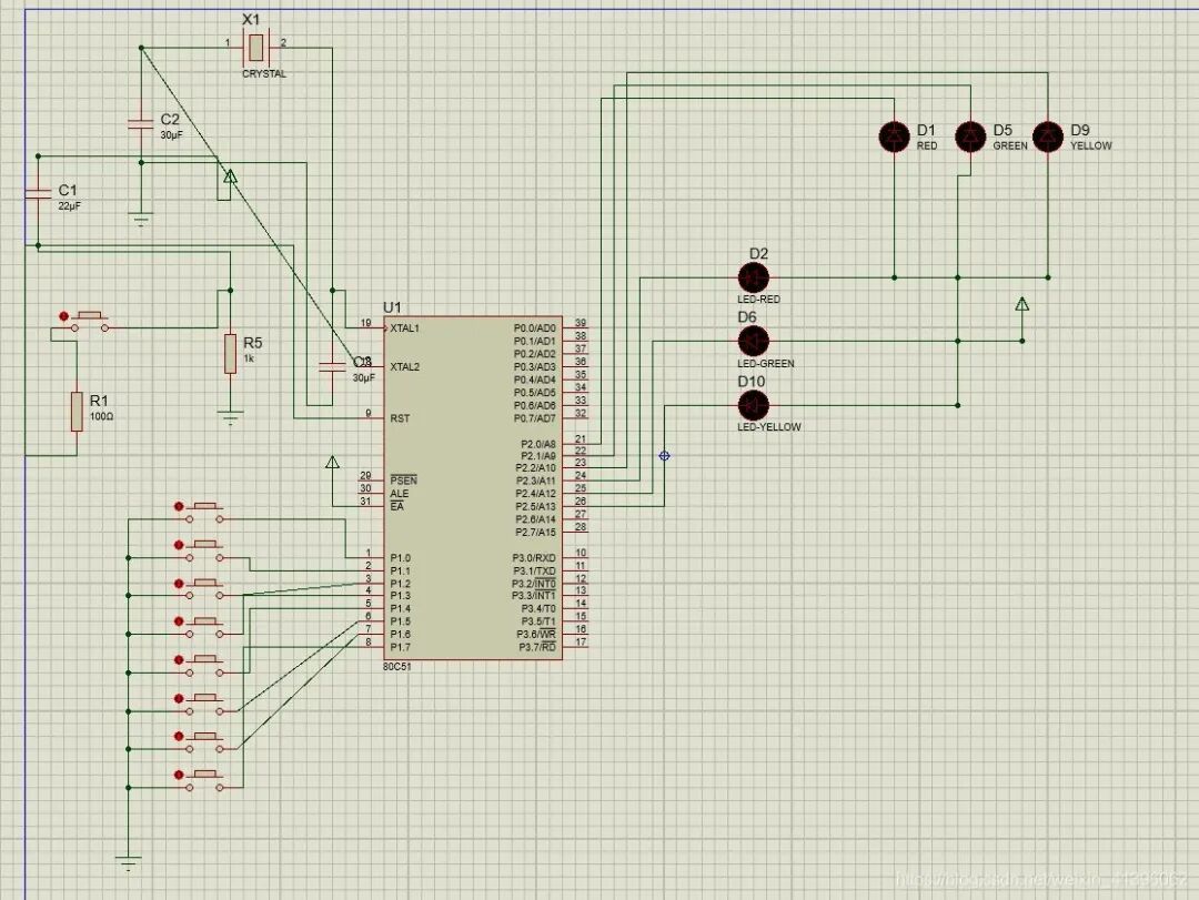
Use ADC to read potentiometer voltage, control PWM to adjust LED brightness.
Generate sine waves through DAC and observe the waveform on an oscilloscope.
2. Advanced Projects
Multi-channel ADC acquisition (e.g., synchronous sampling of temperature and light intensity).
Audio processing: ADC sampling + digital filtering + DAC output.
Mastering the principles and implementation of DAC/ADC is an important foundation for developing embedded systems and IoT devices. It is recommended to practice in conjunction with specific microcontroller manuals (e.g., STM32, ESP32).