
Long press the QR code above to recognize, follow, and click “Skill Improvement” to obtain professional knowledge and free materials.
Share this article to your friend circle and send a screenshot to the public account to participate in the lottery. The prize is a book at the end of the article.

Before introducing the multimeter in detail, let’s first discuss some general knowledge and reading habits for measuring instruments.
Measuring instruments can be divided into analog (pointer), digital, and waveform (graphical) displays for measurement results.
Different types of electrical parameters require corresponding instruments, and the appropriate function setting should be selected. For example, measuring length requires a ruler, and different objects may require different types and accuracies of rulers; the same applies to measuring electrical quantities and parameters.
Some instruments may need to be preheated, adjusted, or zeroed before official use to reach normal working conditions. Then estimate the size of the parameters to be measured and choose an appropriate range to improve measurement accuracy. If uncertain, generally start with a high range to ensure the safety of the measuring instrument.
Range selection is generally based on the pointer being between 1/3 to 2/3 of the full scale, or for digital displays, close to the set value for accuracy. For graphical displays, the profile should be fully visible and as large and clear as possible.
During measurement, it may be necessary to adjust the way the results are displayed, such as levels, magnifications, and other function knobs or switches to facilitate observation and result display. The lock (HOLD) key can lock the measurement result or store the data.
Reading from pointer instruments involves looking at the selected function and range, as well as the scale position indicated by the pointer.
The function setting determines the measurement category and unit, while the range determines the unit and reading.
It is important to know which scale to look at on the dial, generally the corresponding function or the most accurate one, while also observing the pointer’s deflection position for reading.
There are four types of reading relationships: addition, subtraction, multiplication, and division.
Addition and subtraction are most representative in level meters. If selecting +3dB and +10dB, and the pointer points to +6dB, the measurement result is +19dB. If the pointer is at -5dB, the measurement result is +8dB.
Multiplication relationships, such as measuring resistance in ohm settings, if selecting RX100 and the pointer is at 20, then 20 multiplied by 100 equals 2KΩ, meaning the resistance is 2KΩ. For oscilloscopes measuring signal amplitude, if selecting a voltage level of 1mV and the waveform peaks to valleys total 5 divisions, then 1X5 equals 5mV. Thus, the amplitude of this signal is 5mV.
For division relationships, such as voltage and current testing with pointer multimeters, the selected range represents the full-scale value, while the pointer’s deflection indicates how much of that value is occupied. For example, using the DC voltage range of 50V, if the pointer is at 26 on the scale, it indicates that 50V is divided into 5 large divisions, each further divided into 10 small divisions, totaling 50 divisions, occupying 26 of them, resulting in a measurement of 26V.
For digital instruments, readings can be taken directly, with the unit determined by the selected range. Some automatic range instruments will also display the unit.
Knowledge Related to Multimeters
Multimeters can be categorized into two major types based on measurement principles and result display: pointer and digital types. The main differences between the two are as follows.
Digital multimeters are generally more accurate and sensitive than pointer multimeters, with higher internal resistance, making them closer to ideal measurement conditions when measuring voltage. Additionally, digital multimeters have more measurement functions, such as measuring capacitance, temperature, frequency, etc.
When measuring dynamic processes, digital multimeters may not reflect dynamic changes well due to digit changes, while pointer multimeters can effectively reflect continuous changes in quantities and trends, allowing for more intuitive observation of dynamic processes.
When measuring DC voltage or current, if the polarity of the probes is reversed with a pointer multimeter, the pointer will deflect in the opposite direction, whereas a digital multimeter can automatically recognize and display the polarity. If it is a negative value, a “-” sign will appear before the number.
Pointer multimeters may get damaged or lose accuracy when measuring voltage or current in overload situations, as the pointer will deflect to the limit position. In contrast, digital multimeters will display 1, indicating an overload situation, and this applies to resistance measurements as well.
Pointer multimeters require reading based on the pointer and scale, making them prone to human error, while digital multimeters eliminate human error, but they can be affected by interference, and the digit changes can complicate recognizing the value. Generally, a middle value is taken, while in some cases, the minimum or maximum value is used.
The following is the difference shown in Table 1, which is especially important for beginners and should be noted.
Table 1: Relationship Between Probes and Battery Positive and Negative Poles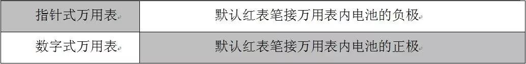
Given that both pointer and digital multimeters have their advantages, it is recommended to have both types available. Overall, digital multimeters are much more user-friendly and should be the first choice.
Pointer multimeter selection tips:
When placing the multimeter horizontally, vertically, or flat, the closer the pointer is to the zero position, the higher the accuracy of the multimeter. Then perform some resistance and voltage measurements to see if the function settings are good and how accurate they are. If necessary, you should also check the user manual.
When measuring various component parameters, connect the black probe to the COM common socket and the red probe to the corresponding socket according to the measurement item, as shown in Figure 1. Different models of multimeters may have different socket layouts and usage.
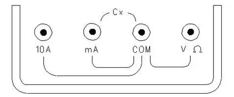
Figure 1: Multimeter Function Sockets
The function markings on the multimeter are as follows.
V and ACV indicate AC voltage settings; A and DCA indicate DC current settings; Hz indicates frequency setting; Ω and OHM indicate resistance setting; HFE indicates transistor setting; F is for capacitance measurement.
Precautions When Using Multimeters
(1) First pay attention to personal safety; the probe wires should not expose metal wires. When measuring voltage or current online, develop a habit of using one hand to operate, holding the probe like chopsticks. To facilitate measuring DC voltage, you can also fix the black probe to the ground position (such as inserting it into the ground spring of the TV cathode ray tube or some heat sink holes connected to ground; using crocodile clips on the ground wire is also acceptable).
During voltage measurement, do not touch the metal parts of the probes and circuit solder joints or component metal parts to prevent electric shock.
(2) Pointer multimeters must be zeroed before use, i.e., the pointer should point to the zero scale.
For the ohm setting, zero adjustment is done by shorting the two probes and adjusting the zero potentiometer to make the pointer point to the right zero scale. Note that each time you change the resistance range, you must perform a zero adjustment.
For voltage and current ranges, adjust the spring of the meter head or the central “I” screwdriver adjustment to make the pointer point to the left zero scale.
(3) When measuring voltage or current, if the two probes are still in the circuit, do not switch ranges or settings, especially under high voltage or high current conditions, as this may damage the multimeter and potentially damage circuit components.
(4) Do not measure resistance while the circuit board is powered (or when large capacitors still have charge), as this may damage the multimeter.
(5) The current setting on pointer multimeters should not be used to measure voltage and resistance while powered, or the large current may damage the meter head. Voltage and current measurements must not be switched incorrectly. If you mistakenly select the resistance or current range for measuring voltage, it may easily burn out the multimeter.
(6) If you find that the digital multimeter displays a battery symbol, or if the pointer multimeter has difficulty zeroing when measuring resistance or the measurement accuracy decreases, this indicates that the built-in battery of the multimeter needs to be replaced. If not used for a long time, the battery should be removed, and for pointer multimeters, the setting should be turned off or set to the maximum AC voltage range to prevent misoperation that could damage the multimeter during the next use.
(7) When measuring resistance, generally do not touch the component leads and the metal parts of the probes, especially when measuring components with high resistance values, as the body resistance in parallel will reduce the resistance value, thus affecting measurement accuracy.
(8) Additionally, it is important to regularly check that your instruments and tools are safe and reliable, and that their measurement functions and accuracy are normal, otherwise, it may cause trouble during the next use and lead to misjudgments resulting in poor outcomes, thus complicating repair and inspection processes.
Various Functions of the Multimeter
The Resistance Range is the Most Widely Used
The resistance range (ohm setting) is generally used to measure the resistance value, check the continuity of circuits and circuit components, and determine the health of components by measuring the resistance between component leads against normal data.
Before using a pointer multimeter, zero it by shorting the two probes. At this time, the pointer will deflect to the right; adjust the zero potentiometer to make the pointer point to the right zero scale. If it cannot be zeroed, using the Rx1 to Rx1k range indicates that the 1.5V battery is low; using the Rx10k range indicates that the 9V or 12V stacked battery is low.
1. Range Selection
The ohm range scale is marked with Ω, with zero on the right and increasing values to the left, with a nonlinear arrangement of scales, where the middle segment displays more accurately. Each time you change the resistance range, you must perform a zero adjustment to ensure measurement accuracy.
Once the resistance value is identified, select the appropriate range and zero it. The principle for selecting the appropriate range is to keep the measurement value pointer as close to the middle of the scale as possible. For example, if the resistance is 10Ω, select the Rx1 range; if the resistance is 220Ω, select the Rx10 range; if the resistance is 4.7kΩ, select the Rx100 range; if the resistance is 68kΩ, select the Rx1k or Rx10k range. Place the probes on the two leads of the resistor being measured, read the resistance scale (the topmost scale line) indicated by the pointer, and then multiply by the range factor to get the resistance value.
If using a digital multimeter, the closer the measured component’s resistance is to the selected range, the more accurate the measurement result. For example, for a 150Ω resistor, both Rx200 and Rx2k ranges can be used for measurement, but the 200 range will provide more accurate results.
2. In-Circuit Measurement
Most repairs require measuring resistance directly on the circuit board. In-circuit measurements may be influenced by other series or parallel components, leading to deviations in measurement results. It is generally necessary to swap the probe connections and measure twice, taking the larger measured resistance value as a reference. For example, measuring an 82kΩ resistor (see Figure 2), if the measurement shows a value less than the nominal and not significantly different, this indicates that the resistor is normal. If the measured resistance is greater than the actual resistance value, it may indicate that the resistor has increased in value; if the measured value is very small, such as with parallel low-resistance resistors or inductive components, it is necessary to desolder the leads or remove the component for measurement.
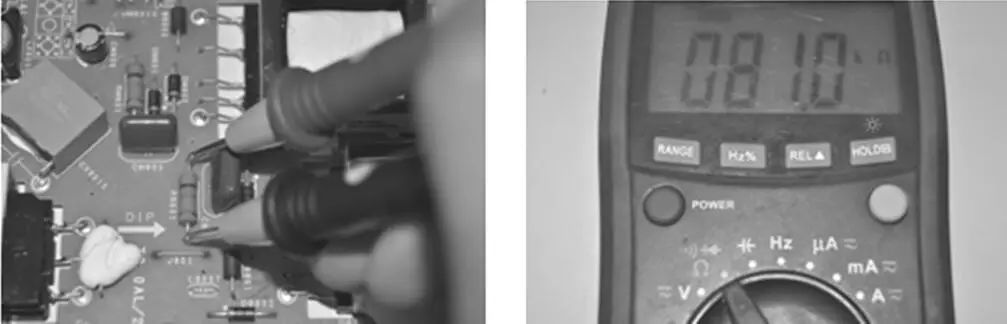 Figure 2: Measuring 82kΩ Resistor In-Circuit
Generally, resistance values may increase due to high currents or other reasons leading to an open circuit, while decreasing resistance values are rare.
Note
When measuring components in-circuit, generally the leads should be disconnected, and large capacitors, high-voltage capacitors, high-voltage packs, cathode ray tubes, and other charge-storing components should be discharged before measurement. There are many methods for discharging, such as directly shorting the component leads, using a 1kΩ or 10kΩ, 2W resistor for discharge. The author recommends using a soldering iron for discharge a few times, that is, using the soldering iron’s plug to connect to the discharge point.
When there is a significant discrepancy in data during in-circuit measurements, it is necessary to analyze the condition of the circuit where the components are located. When there are semiconductor devices in parallel, it can affect the resistance value.
When measuring diodes and transistors with the ohm setting in-circuit, if the forward and reverse resistance values are very low, and there are no low-resistance components in parallel, the PN junction may be shorted. If both forward and reverse resistance values are high, it indicates an open circuit.
It must be pointed out that due to the nonlinear V-I characteristics of diodes, measuring the resistance of diodes with different resistance settings on the multimeter will yield different resistance values, for example, the R×100 setting will yield a higher measured value than the R×10 setting.
Measuring the resistance of long copper foil lines on a PCB can indicate whether there is an open circuit. It can also determine whether two points on the circuit belong to the same line. When there are discrepancies in the measured resistance values, the component leads can be cut, the copper foil can be cut for measurement, or one or two leads of the component can be desoldered or removed entirely for measurement.
Knowledge Expansion
It is important to note that some component leads may be oxidized, and circuit board solder joints may be oxidized or covered by chemicals; thus, scraping the leads or solder points may be necessary. You can also press and slide the probe tip on the solder point or scrape off the solder mask green oil from the copper foil to ensure good probe contact for accurate measurement, otherwise, it may lead to open circuits, increased resistance values, or suspected poor contact misjudgments.
A circuit or component has a certain resistance value; measuring its resistance value with the ohm setting can help determine its condition. However, this measurement only reflects certain aspects and parameters of the component’s condition and is not comprehensive. Understanding from another angle, measuring with a multimeter may indicate that a component is good, but it may not function normally in an installed state. For instance, a diode may exhibit reverse leakage, increased forward resistance, or poor rectifying characteristics when installed. A transistor may have insufficient amplification or poor frequency characteristics, or soft breakdown may occur.
For example, if you measure a PN junction’s forward resistance using a low resistance setting, and it appears too high, but re-measuring with the R×1k setting shows normal, it indicates that the characteristics of this component have deteriorated, and it may not work normally or stably in the circuit.
Regardless of the type of component being measured, learning from materials or others’ experiences, or disassembling components to understand their internal structure and working principles, is very beneficial for measurement, and certainly beneficial for circuit analysis and repair.
A good method for measuring components is: during your initial learning phase or when encountering difficulty in judging their condition, select a known good component and compare it with the component to be measured for accurate judgment.
Lastly, I hope everyone will engage in extensive hands-on practice to solidify the foundation. Repeating simple tasks will definitely lead to proficiency, allowing you to face difficulties and challenges calmly and easily resolve them.
Using the DC Voltage Range
Estimate the size of the voltage to be measured and select the appropriate range. If the circuit voltage level is unknown, start with the maximum range; if the range is too high, switch to an appropriate range for measurement.
Connect the black probe to the circuit negative or ground, and the red probe to the measurement point, then read the voltage value based on the selected range and pointer deflection. This measures the voltage from the point to ground, and another case is measuring the voltage from point to point, such as measuring the voltage drop across a diode or the voltage between the base and emitter; if the pointer deflects negatively, it indicates that the probes need to be reversed, or the circuit may be powered by a negative supply or in an oscillating state or reverse-polarity driving circuit.
Use a digital multimeter to measure voltage as shown in Figure 3:
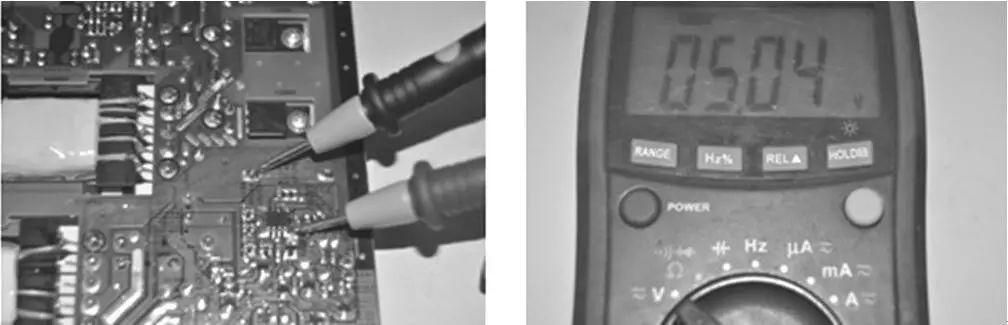 Figure 3: Measurement After 5V Voltage Regulation
The current and voltage range scales represent the total range for the selected setting; for example, if selecting the 10V range, and the pointer points to two divisions to the right of 4, it indicates 4.4V, as this scale is linear, with each large division further divided into 5 small divisions, so you should be able to calculate this. A digital multimeter displaying 1 indicates an overload, requiring a switch to a higher range for testing.
If the probes are reversed on a digital multimeter, it will display a negative sign. If a negative voltage is displayed with the probes connected correctly, consider what type of circuit it is and what characteristics the signal has. Many things require you to think for yourself about why.
Experience Sharing
If many DC voltages measured on the circuit board do not match the reference values, it may be due to a broken ground connection.
Knowledge Expansion
For repairs, the first step is measuring the voltage at some key work points, such as the power outputs of the circuit supply, output voltage of the voltage regulation IC, midpoint voltage in OCL, and power pins of the chip, to determine whether the related circuits are functioning normally.
Using the AC Voltage Range
The measurement method is similar to that of the DC voltage range; select the appropriate range based on the circuit voltage, and the probes do not need to be connected in a specific polarity. The reading method is the same as that for DC voltage.
When measuring mains AC voltage of 220V, use the 250V AC voltage range, and pay attention to personal safety; do not touch the metal parts of the probes and the metal parts of the circuit being measured. Measurement is shown in Figure 4.
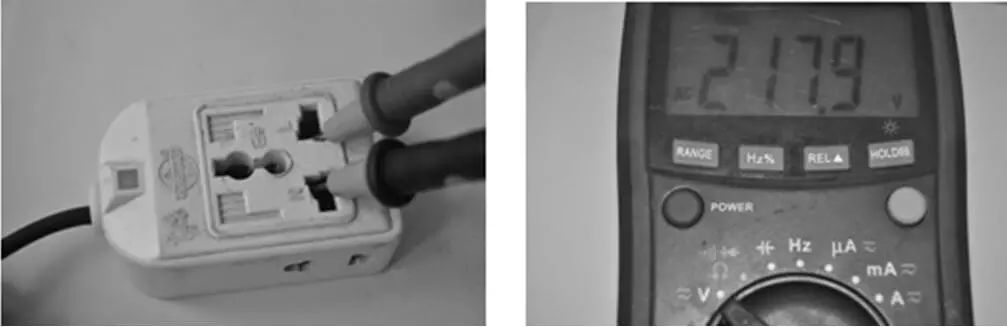 Figure 4: Measuring 220V Power Supply
Experience Sharing
If the zero line of the 220V AC is disconnected, measuring with a test pen will show both wires carrying voltage.
Using the DC Current Range
Disconnect the circuit at the measurement point, which can be done by disconnecting component leads, cutting copper foil, or unsoldering dedicated measurement points. Estimate the size of the current to be measured (if unknown, start with the maximum range), choose the appropriate range (following the same principles as resistance range selection), connect the red probe to the current output end of the circuit and the black probe to the current input end of the circuit. If uncertain, briefly connect the probes to check; if the pointer deflects negatively, swap the probes for measurement. Note that the probes must not be connected in parallel across the component leads, as this may damage the multimeter. Then read the current value based on the selected range and pointer deflection.
When measuring with a digital multimeter, if the probes are reversed, the screen will display a negative sign.
Another method to indirectly measure the current in the circuit is to measure the voltage across a resistor using the voltage range of the multimeter, and calculate the current flowing through that resistor based on Ohm’s law. Alternatively, consider if you can add a limiting resistor to indirectly measure in the absence of a resistor.
Using the AC Current Range
The measurement method is similar to that of the DC current range, but the probes do not need to be connected in a specific polarity. The reading is based on the pointer position on the scale marked with the AC symbol “ac”. When measuring AC current, it is generally for high-power appliances and devices. In practice, using a clamp meter is more convenient, but note that the clamp meter can only clamp one wire.
Using the Capacitance Range
Pointer multimeters can only roughly detect the health of capacitors (not suitable for determining the capacitance of small capacitors with reduced capacity or open circuit faults) and estimate the size of the capacitance; accurate capacitance measurements typically require a digital multimeter, capacitance meter, or specialized capacitance measuring instruments.
When using a digital multimeter to measure the capacitance of capacitors, set the digital multimeter to the capacitance range and select the appropriate range based on the capacitance size. After fully discharging the capacitor to be measured, insert it directly into the testing hole or connect the two probes directly to the capacitor leads for measurement. The display of the digital multimeter will directly show the capacitance of the capacitor being measured.
If the displayed value equals or is very close to the nominal capacity, it indicates that the capacitor is normal;
If the displayed capacitance is significantly lower than the nominal capacitance, it indicates that the capacitor’s capacitance has decreased and cannot be used.
If the capacitance to be measured exceeds the measuring range of the multimeter, displaying 1, then this digital multimeter cannot be used for measurement; instead, another suitable multimeter or a specialized capacitance meter should be used.
Using the Diode Range
When using a pointer multimeter for measurement, generally select the R×100 range. The red probe (negative pole of the internal battery) represents the N pole, and the black probe represents the P pole. When the diode is conducting, the pointer indicates the resistance value of the conducting diode, with the black probe connected to the P pole (positive side). If the pointer does not move in both forward and reverse measurements, it indicates that the diode is open; if both forward and reverse resistance values are near 0, the diode is shorted; if the pointer deflects during reverse measurement, it indicates reverse leakage. All three cases indicate that the diode is defective and cannot be used in the circuit.
When using a digital multimeter for measurement, the red probe (positive pole of the internal battery) represents the P pole, and the black probe represents the N pole. The displayed number indicates the forward voltage drop of the diode: silicon diodes range from 0.5 to 0.7V, and germanium diodes range from 0.15 to 0.3V. If both forward and reverse measurements display “000” or very low values, the diode is shorted; if both forward and reverse measurements show 1, it indicates the diode is open; if there is a certain voltage value during reverse measurement, it indicates reverse leakage of the diode.
When a diode conducts in the forward direction and blocks in the reverse direction, the diode is considered good.
Currently, there is a diode on the circuit board; please refer to the measurement results shown in Figure 5 and make a judgment on whether this diode is a good one.
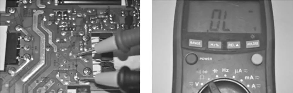 Figure 5: Diode Measured In-Circuit

Measurement Notes
A component’s condition can be determined in-circuit or by removing it from the circuit; this generally refers to measuring resistance in-circuit. Components can also be identified in a powered state by measuring voltage. Why?
Components are generally tested using the resistance range of the multimeter, judging their condition based on their resistance values. However, since components have multiple parameters, it may not be possible to determine that a component is good based solely on resistance; some components may fail upon powering, have insufficient amplification, or exhibit deteriorated frequency characteristics.
When performing measurements, it is essential to engage in thoughtful analysis, considering why things are the way they are, and applying learned knowledge to analyze phenomena and clarify encountered difficulties. Moreover, learning to analyze key testing points in various circuits and measuring electrical parameters to assess circuit functionality, and identifying the causes of abnormalities, specifically which components are damaged, is crucial. Through extensive and methodical practice, improvement in skills is bound to follow. Keep up the effort!
(-END-)
Excerpt from “Crossing Thinking, Electronic Technology Reader”

 Long press the QR code to recognize and purchase
Previous Highlights
Three minutes on stage, ten years of work off stage; mastering electronic technology teaches you to analyze circuit diagrams!
How to Read PCB? You will understand after reading!