Please follow the WeChat official account and Toutiao account “Finger Motorcycle” to read the latest motorcycle maintenance and repair news in real-time. Please search for ID mscmoto directly in WeChat to follow!
The oscilloscope is a device widely used in electronics, electrical engineering, appliance repair, and specialized teaching in schools. With the advancement of technology in the motorcycle industry and stricter national emission regulations, more and more electrical components are being installed in motorcycles. Traditional repair methods struggle to cope with these electrical components, especially with the upcoming National IV emissions standard, which has clearly indicated that the era of fully electronic fuel injection motorcycles is imminent.
In order to improve the repair skills in the domestic motorcycle after-sales service industry, the official website of the National Motorcycle Repair Technology Club, “Motor China”【motomsc.com】, has taken the lead in conducting public training courses on the basic applications of oscilloscopes in motorcycle fault diagnosis and repair.
What is an Oscilloscope?
An oscilloscope is a device that continuously displays voltage (current) changes over time. In the motorcycle repair industry, it can be used not only for detecting circuit faults, in conjunction with various active probes, but also to expand the detection range to mechanical parts, such as intake manifold pressure, cylinder pressure, valve timing, engine combustion status, and more. In the repair of electronic fuel injection systems, the oscilloscope can cover fault areas that diagnostic tools cannot reach. It can be said that the ultimate weapon for fuel injection repair is the oscilloscope.
Although the oscilloscope comes with a user manual, it is overly specialized, and many functions are unnecessary during repairs. Therefore, we will use images to explain the various basic functions of the oscilloscope that are needed in repairs.

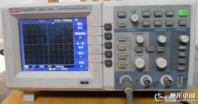
This is the appearance of the oscilloscope from the public group purchase on Motor China, which is slightly different from the oscilloscope demonstrated in this post; just pay attention to the button positions.
First, we must understand that the oscilloscope can withstand an input voltage of 300V, so under normal circumstances, it will not suffer breakdown damage, and it can be operated safely. Just be careful to choose the corresponding probe according to the different measurement states.
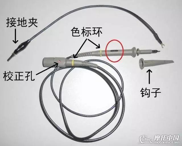
Each standard dual-channel oscilloscope comes with 2 probes, and both ends of the probes have colored rings to indicate which channel the line belongs to and where it is connected. Otherwise, when using both lines together, they can easily be confused. These color rings can be removed and replaced, and the oscilloscope packaging includes multiple color options.
At the oscilloscope end, there is a small hole for calibration, which will be explained later. On the testing end, there is a switch to adjust the magnification, marked with “1X” and “10X”. Pushing it to the corresponding position represents the respective magnification. Magnification refers to attenuation. 1X means no attenuation, while 10X means the voltage is reduced by ten times; for example, an actual voltage of 100V is transformed into 10V.
Therefore, to ensure the accuracy of the display, the oscilloscope is equipped with a corresponding magnification adjustment function. The original ground clip is thin and short, making it unsuitable for repair use. Thicker wires can be used instead, with the length depending on personal preference; I use a 25cm extended ground wire. The ground wire can be easily removed from the probe; heat the original wire with a soldering iron and replace it with a suitable wire. The probe tip is a hook that reveals itself when pulled down, and the hook can be removed to use only the sharp needle. Remember, whether using the hook or the sharp needle, the probe must reliably contact the metal part of the wire to be tested.
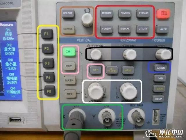
The oscilloscope panel has many buttons. The red light in the upper right corner is the pause button; pressing it stops the operation, and pressing it again turns it green for normal operation. The metal piece in the lower right corner is for calibrating the probe.
The yellow box contains option buttons, and the brown box contains the “SELECT” button, which is used to select the cursor to be adjusted. The white knob adjusts the cursor position, and there is a “COARSE” button that can be ignored.
The pink box contains the selection for channels 1 and 2; pressing it will light up the corresponding green light, and the screen will display lines—blue for channel 1 and yellow for channel 2. To turn off a channel, press the corresponding “CH1” or “CH2” button, and that channel will be turned off, and the line will disappear. The “MATH, REF” buttons below are not needed and can be ignored.
The red function button box contains the “MEASURE” data selection button, the “CURSOR” cursor use button, and the “UTILITY” auxiliary function button, which is needed once when you first get the oscilloscope and is generally not used afterward. The other three buttons are not needed and can be ignored.
The black box contains three knobs that are used every time: the left knob adjusts the waveform line height, the middle one adjusts the waveform’s left-right position on the screen, and the right one adjusts the stability, also known as the “trigger release suppression”.
The white box contains two large knobs; the left one adjusts the voltage value, with each square representing how much voltage; the right one adjusts the time value, with each square representing how much time.
In the green box below, the left “X” channel is channel 1, and the “Y” channel is channel 2.
The blue box on the right contains the “MENU” button, which is frequently used. Other keys and ports not mentioned can be ignored as they are not needed.
The oscilloscope’s greatest function is waveform testing; it also has voltage testing capabilities, but do not expect to replace a high-precision multimeter with an oscilloscope. The oscilloscope allows for a 5% voltage measurement deviation, so in this regard, its voltage measurement accuracy is not even as good as a cheap multimeter. Fortunately, we only use it to test waveforms, so small deviations in voltage can be ignored.
When the machine is received, remember to check if the power socket has a grounding wire; the oscilloscope requires a grounded three-prong socket. If using a two-wire 220V power line, it is strongly recommended to add a grounding wire by connecting the ground wire terminal in the socket with a wire, taking a discarded large screwdriver, wrapping the wire around the metal rod of the screwdriver, and driving the screwdriver into the ground in the corner of the wall. After that, pour some saltwater over it to complete the task. If there are water pipes or large iron doors in the room, tying the wire to these metal objects is also acceptable.
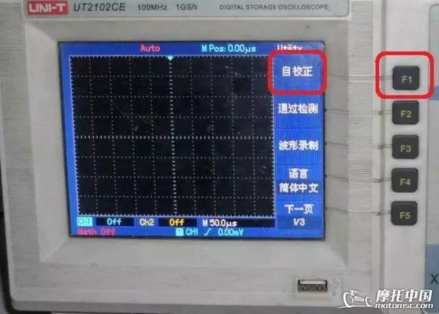
Next is to power on; the power button is located at the top left of the machine, marked with “OFF, ON“. Press it to turn on. After turning on, wait for 15 minutes to allow the machine to warm up. Whenever using the machine, it is best to preheat for a few minutes if conditions allow. Then press the “UTILITY” auxiliary function button, and the screen will change like this.
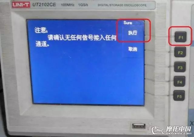
Press the “F1” key to execute the self-calibration program, and the machine will automatically test its internal programs.
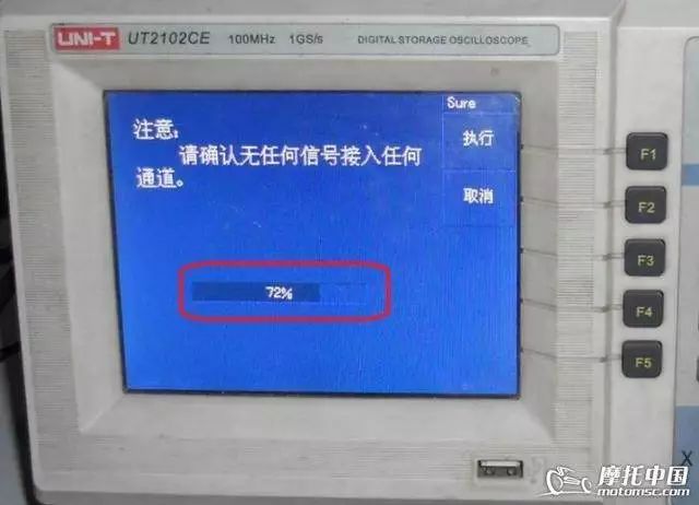
During the machine’s self-calibration, a progress bar will appear. All you need to do is wait a moment; the calibration will generally complete within a few minutes. For future use, calibrating once a year is sufficient. Next, start installing the probes and calibrating the probes.
Extended Reading:
The oscilloscope repair mode is the advanced path for motorcycle repair, a treasure in the fuel injection era.
The oscilloscope is the magnifying glass in the ignition system.
Oscilloscope repair case: Scooter startup jitter fault.
Official WeChat subscription account of Motor China

WeChat ID: mscmoto

Long press the QR code to recognize and reward