For more exciting content, please click the blue text above to follow me!
—————————————
Research Journey
With a firm understanding of cutting-edge technology, I reminisce about my deep research during my spare time. I often write articles on my computer, ensuring to publish one every day. As the months pass, my passion grows stronger, and my thoughts flow like sweet steam buns. I hope you can lend your support and strength, as I respect and cherish all constructive feedback.
—————————————
I2C (Inter-Integrated Circuit) originated from an early design by Philips, which consists of two lines, namelySDA and SCL signals. The I2C specification clearly defines that this bus supports five different speed modes. In practical use, the choice of mode depends on specific circumstances; there is no absolute good or bad among the five modes:
1) Standard Mode (SM):
Maximum speed of 100kbit/s, maximum capacitance 400pF, open-drain drive type, bidirectional transmission.
2) Fast Mode (FM):
Maximum speed of 400kbit/s, maximum capacitance 400pF, open-drain drive type, bidirectional transmission.
3) Fast Mode PLUS (FM+):
Maximum speed of 1Mbit/s, maximum capacitance 550pF, open-drain drive type, bidirectional transmission.
4) High-Speed Mode (HS):
When the bus distributed capacitance is 400pF, the maximum speed can reach 1.7Mbit/s; when the distributed capacitance is 100pF, the maximum speed can reach 3.4Mbit/s.
5) Ultra-Fast Mode (UFM):
Speed can reach 5Mbit/s, push-pull drive type, unidirectional transmission, incompatible with other modes.
The following diagram shows the operation timing diagram of the clock chip RX – 8025T:
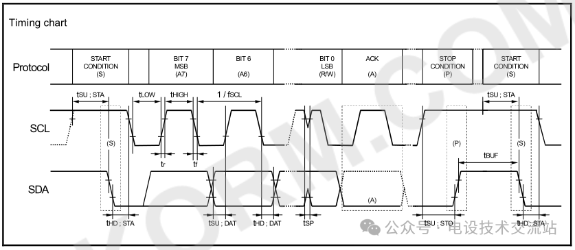
All communication characteristic data can be divided into the following features:
1, Start Condition (S):
When the SCL line is high, a signal transitioning from high to low on theSDA line is recognized as the start condition, which is the first condition for initiating data transmission. Regardless of how many start conditions are issued, the last one prevails.
2, Stop Condition (P):
When theSCL line is high, a signal transitioning from low to high on theSDA line is recognized as the stop signal. Once this condition is detected during transmission, any previous operations will stop, waiting for subsequent operation instructions.
3, Bus Acknowledge (A):
The receiving end responds to the sender by pulling theSDA line low, with ACK being a low-level signal indicating successful reception. If the receiving end sends NACK, the data transmission will terminate.
4, Address Transmission:
Supports both 7-bit and 10-bit addressing modes.
In 7-bit addressing mode, the high 7 bits of the address frame represent the slave address, and the 8th bit determines the data transmission direction.
In 10-bit addressing mode, the master sends a frame, with the first frame sending the header sequence, followed by the second frame sending the low eight bits of the slave address.
The previously shared clock chip RX – 8025T has inherent chip addresses and read data register addresses, all of which fall under address-type data.
5, Data Transmission:
WhenSCL is low, theSDA changes; when SCL is high, SDA remains stable. Each clock cycle sends one bit of data, with a data frame length of 8 bits, and each 8 bits byte transmission is followed by an acknowledge bit (bus acknowledge (A)).
Our designed electronic clock has basic functionalities, but it still lacks practicality. Consider this: if the clock is installed and debugged, but the preset alarm time is not implemented, how can we set the alarm, adjust the alarm time, and accept multiple preset alarms within 24 hours? Look at today’s smartphones, which can design multiple alarms simultaneously, and when the preset time arrives, the alarm will ring.
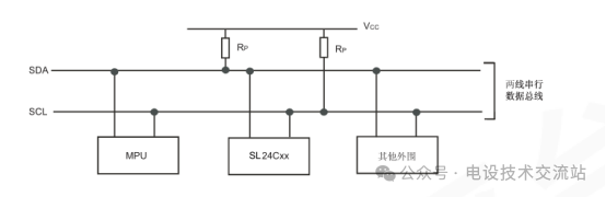
Based on this idea and in conjunction with the bus specification, we connect a memory (I2C serial bus EEPROM) to the I2C bus. After selection, we chose SL24C02 (with a capacity of 2kBit; if more data is needed, a larger capacity can be selected), and the wiring diagram is shown above, where “other peripherals” refers to our clock chip, thus enabling the storage function for preset alarm times.

SL24C series belongs to electrically erasable programmable read-only memory (EEPROM), which transmits data via theI2C serial bus. The interface requires only two lines: the serial data line (SDA) and the serial clock line (SCL), enabling communication with the host controller, simplifying hardware design and reducing wiring complexity.
For presetting the alarm, we can add 2 buttons or connect the microcontroller’s serial port (UART) to a computer to set the preset alarm time. These hardware changes will also require software adjustments, which will be shared in future articles due to space limitations.
 Creating is not easy; thank you for your attention, likes, and shares!
Recommended classic articles from the past:
1、Do you understand these electrical parameters of power supplies?
2、Do you know how much impact an unsuitable power supply has on devices?
3、Why do electronic devices need to be designed with enclosures, and what factors should be considered in enclosure design?。
4、Essential functions that embedded uCOS-II software development engineers must master.。
5、Assembly code for a two-wire universal driver chip, with a simple program structure and classic content!
Since you are here, please give a thumbs up before you leave!~~~