Using a multimeter to measure circuit faults is one of our common methods. Here, I will discuss how to use a multimeter to check for circuit faults.
When we check for circuit faults with a multimeter, we mainly use three ranges of the multimeter for measurement:
First, use the resistance range to measure the resistance value of the circuit or use the multimeter’s buzzer function to check the continuity of the circuit;
Second, use the voltage range to measure the voltage levels in the circuit, including DC voltage and AC voltage;
Third, use the current range to measure the size of the current in the circuit.
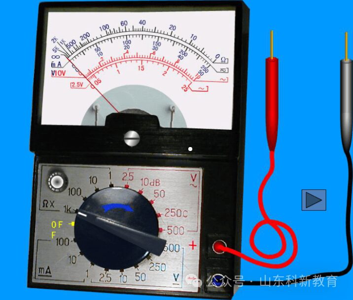
First, let’s talk about measuring resistance with a multimeter. When measuring the circuit, the resistance value in the circuit often reflects whether the circuit is normal. Therefore, it is very important to use the multimeter correctly to measure resistance. When measuring resistance, the multimeter needs to be zeroed in two steps: first, set the ohm scale to zero; second, mechanically set to zero. After zeroing, you need to select the appropriate resistance range. For analog multimeters, when the needle points to the middle of the scale, the range is considered appropriate. A common mnemonic to remember this point is: “Measure accurately, the needle should be in the grid.”
During measurement, the meter needle must have good contact with the circuit being tested to minimize the effect of contact resistance on the measurement value. When measuring in a circuit with a large resistance, do not let both hands touch the circuit being measured, as this could parallel the resistance of our body to the circuit, leading to misjudgment or interference in identifying circuit faults.
For detecting circuit faults using the voltage range of a multimeter, we first need to determine the type of voltage in the circuit: is it DC voltage or AC voltage? If it is DC voltage, the black probe of the multimeter should be placed at the low potential of the test point, and the red probe should be placed at the high potential of the test point. It is important to note that the multimeter is connected in parallel with the circuit being tested.
When measuring AC voltage, we can place the probes on the neutral line, and the red probe should be placed at various points along the circuit. Under normal conditions, it should display the corresponding voltage value. If the voltage value is zero, it indicates a circuit fault. For current measurement, the multimeter is generally connected in series with the circuit being measured. If it is DC current, the black probe should be connected to the low potential, and the red probe should be connected to the high potential.
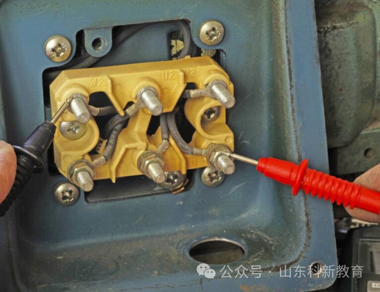
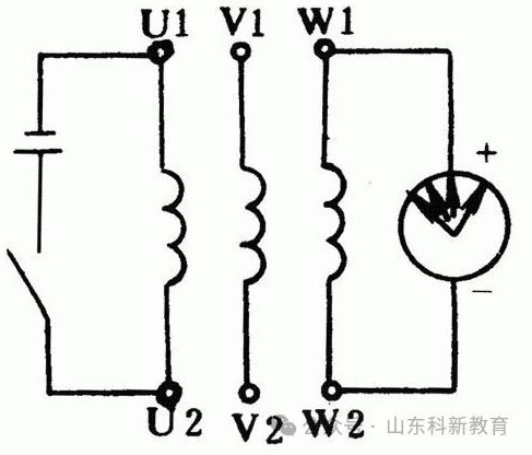
Next, let’s discuss the second question: when a motor does not have a nameplate, we can use a multimeter to measure the number of poles and the speed of the motor. We can use the milliamp range of an analog multimeter, placing it at the ends of the motor winding, and then manually rotate the rotor of the motor to observe the number of times the needle swings. If the needle swings once, it indicates a two-pole motor; if it swings twice, it indicates a four-pole motor, and so on.
After determining the number of poles of the motor, we can use the formula n=60f/p to roughly calculate the speed of the motor. In this formula, f=50 Hz, and P is the number of pole pairs. If it is a two-pole motor, its speed will be 3000 revolutions per minute, and for a four-pole motor, it will drop to 1500 revolutions per minute.
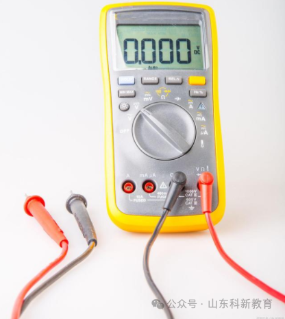
Finally, let’s talk about using a multimeter to measure cable breakpoints. If it is a single wire, we can set the multimeter to the DC 20V range, use the red probe to detect the surface of the wire, and wrap the black probe around our finger a few times to detect the change in induced voltage. If the induced voltage changes uniformly, it indicates that the circuit is intact; if a sudden drop in induced voltage occurs, it indicates a poor connection at that point.
Source: This article is reprinted from the internet, and the copyright belongs to the original author. If there are any copyright issues, please contact us for deletion. Thank you!

Scan to Follow
WeChat ID|13615417996
Follow the QR code on the left for free access to
【Siemens Resource Collection】