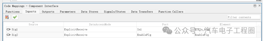
If the code generation configuration file option selected is ert.tlc, usable embedded code can be generated. However, if autosar.tlc is selected, the generated code will report an error indicating that the input and output ports are not mapped. To resolve this issue, we need to perform mapping of the input and output interfaces.
Of course, the prerequisite is that you need to configure whether it is an AUTOSAR SR interface or an AUTOSAR CS interface. This article focuses on how to configure the AUTOSAR CS interface, as detailed below:
1 What is an AUTOSAR CS InterfaceIn AUTOSAR, the Client-Server (CS) interface is a core communication mechanism used to achieve “request-response” interactions between software components (SWC). It is similar to function calls in traditional programming, but standardized under the AUTOSAR framework to meet the high reliability, reusability, and cross-ECU collaboration requirements of automotive electronic software.The essence of the AUTOSAR CS interface is a standardized “function call” protocol, defining a service contract between a pair of software components:
- Client: The party initiating the service request (similar to a function caller).
- Server: The party receiving and processing the request, returning results (similar to a function definition).
- Operation: The specific service content (similar to function implementation logic), with each method having a unique identifier (Service ID) and parameter list (input/output/input-output parameters).
The difference from traditional function calls is that the calling process of the CS interface is managed by the AUTOSAR Runtime Environment (RTE), rather than direct code jumps. The RTE is responsible for encapsulating communication details (such as signal routing, task scheduling, error handling), allowing the client and server to be unaware of each other’s actual location (same ECU or different ECUs) and implementation details (such as whether running in RTOS).
The core role of the CS interface is to decouple and standardize communication.
The client and server interact through the interface “contract” without directly depending on each other’s internal implementation. The CS interface is “stateful”: the server can maintain internal states (such as caches, counters) and dynamically adjust behavior based on client requests (for example, multiple calls to the “set parameter” method will accumulate effects). This complements the Sender-Receiver interface (which only transmits data and is stateless). The definition of the CS interface follows the AUTOSAR meta-model (ARXML file), ensuring compatibility of code and configurations generated by different tools (such as Simulink, DaVinci Developer, CANoe). For instance, the CS interface defined in Simulink can be directly exported as ARXML for parsing by other AUTOSAR tools.
2 Understanding the AUTOSAR CS Interface
To gain a deeper understanding of the AUTOSAR CS interface based on Simulink, here is a clear analogy:
The customer is like the client, the waiter is like the CS interface, and the kitchen is like the server, while the dishes on the menu correspond to operations.
You (the customer) call the waiter (CS interface) and say, “I want a steak (operation), medium rare (parameter).” The waiter passes your request to the kitchen (server); the kitchen starts cooking, and during this time you must wait; finally, the waiter brings you the cooked steak (return result). This process is a typical CS interface call: there is a request, processing, waiting, and response.
Corresponding to an example in automotive ECU software:
source: https://www.cnblogs.com/Ye-Wei/p/17208050.html
Assuming there is a central body controller in a car (acting as the client), which needs to interact with several other ECUs (acting as servers), for example, to control the window lift, then:
-
Client: The body controller (receiving the signal when you press the switch)
-
Server: The window motor controller
-
Operation:
<span><span>MoveWindow(position, direction)</span></span>
<span><span>You press the window up switch on the driver's side, and the body controller (client) calls the window motor controller (server) through the CS interface to execute the </span></span><span><span>MoveWindow</span></span> operation, with parameters:<span><span> position=driver's side</span></span>, <span><span> direction=up; </span></span> the window motor controller receives the request and starts execution, while the body controller waits for the execution result; after the window motor controller completes the execution, it replies through the CS interface with a result: “Operation completed” or “Obstacle encountered, stopped”; the body controller receives the reply, knows the operation is finished, and may light up an indicator or ignore the obstacle alarm.
The role of the CS interface here is to: ensure that the body controller can command another ECU to perform an action and confirm whether the action was successfully executed. If using the SR interface, the body controller can only continuously send “up” signals but cannot know whether the window is actually moving or has reached its position.
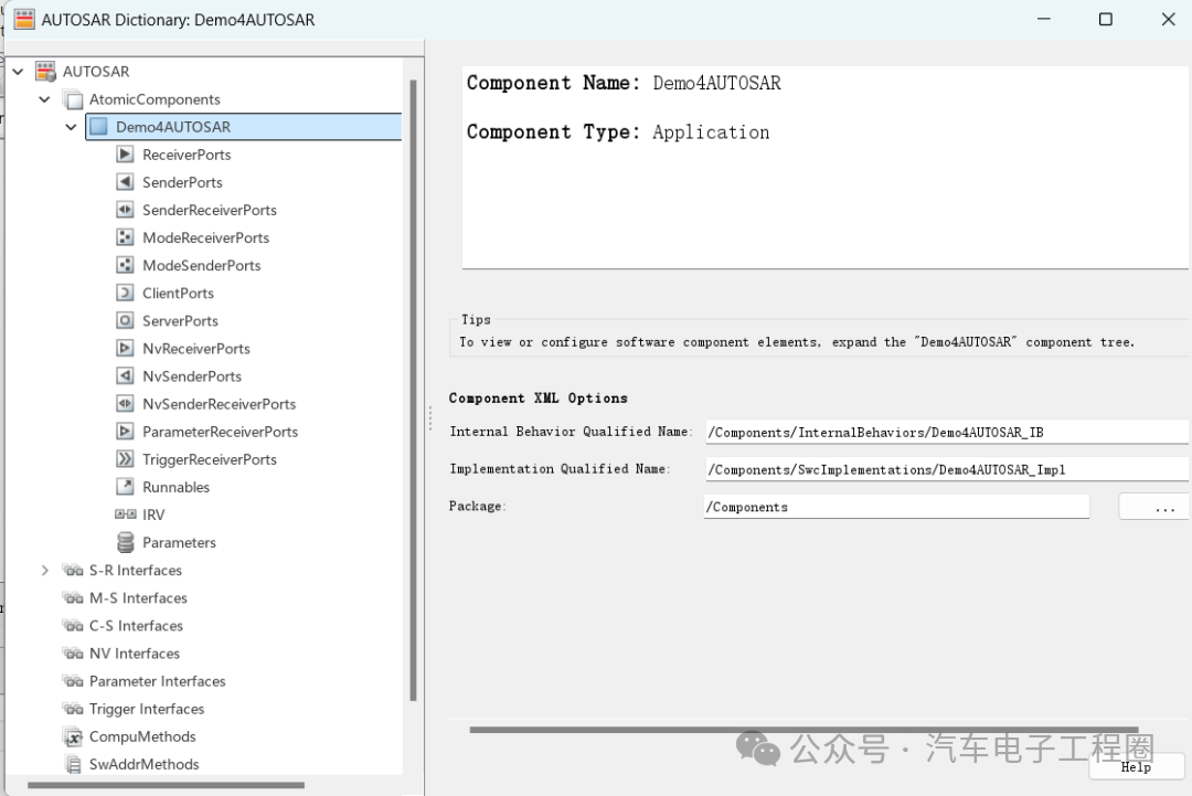
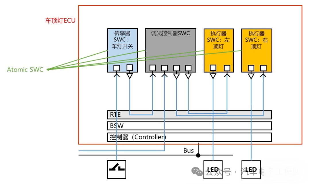
3 Steps to Configure and Use CS Interface in SimulinkAfter understanding the basic information about the AUTOSAR CS interface, we will start practical usage in Simulink, here are two common functionalities: obtaining a temperature sensor signal and sending an IO drive enable signal.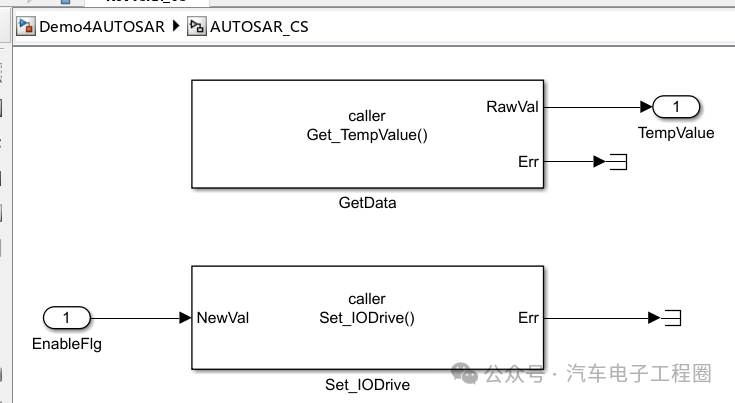 Next, we proceed with the configuration and usage of the AUTOSAR CS interface, the steps are as follows:Step 1: Open the AUTOSAR dictionary, in the C-S interface view, click the Add button. This action will open the “Add Interface” dialog, where you can name the new CS interface and specify the number of operations associated with this interface, keeping other parameters at their default values, as shown below:
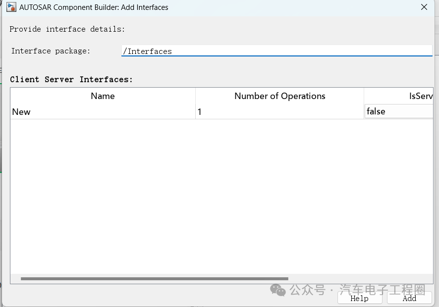 After clicking Add, the new interface will appear in the C-S interface view, as shown below:
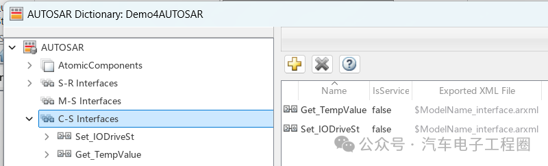
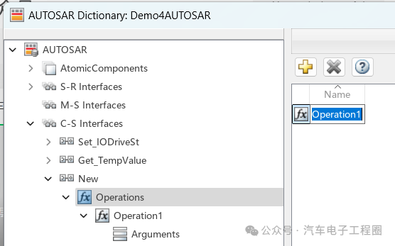
Step 2: Add operations under C-S Interfaces, that is, select Operations, in this view, click the Add button. This action will open the “Add Operation” dialog. In the dialog, enter the Operation Name.

Step 3: Add parameters for the AUTOSAR server operation, that is, expand Operations, expand the specific operation (for example, <span><span>SetNewData</span></span>), then select Arguments, and add parameters corresponding to the Simulink server function prototype.
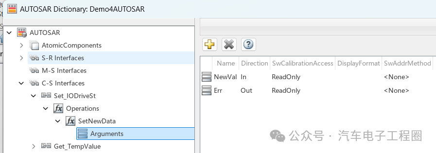
Simulink server function prototype:
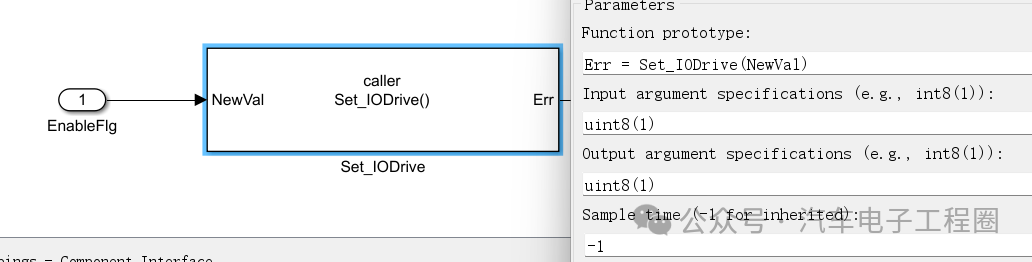
Step 4: ExpandAtomicComponents, expand the specific component being configured, then select ClientPorts. In the client port view, click the “Add” button, which will open the “Add Port” dialog, where you can name the new client port and select a CS interface, then click “Add”; the new port will appear in the client port view.
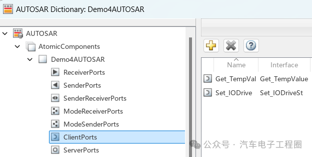
This step completes the configuration of the AUTOSAR client in the configured AUTOSAR dictionary view.
Step 5: Switch to the configured code mapping editor view and map the Simulink function caller to the AUTOSAR client port and CS operation. That is, open the code mapping editor, select the “Function Caller” tab, click the “ClientPort” field, select a port from the available AUTOSAR client port list, and click the “Operation” field to select an operation from the available AUTOSAR C-S operation list.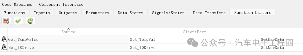
To validate the AUTOSAR component configuration, click the “Validate” button. If errors are reported, please fix the errors and retry validation, repeating this process until validation is successful.
Step 6: Generate C code and ARXML code for the model, as shown below:
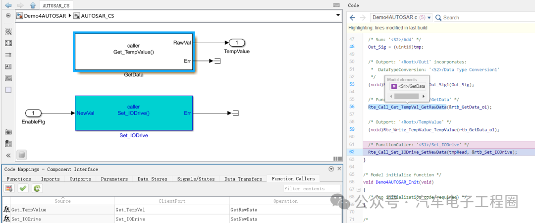
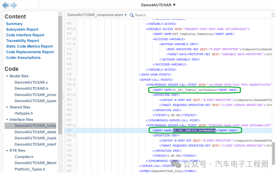 Upon closer inspection, you can see that RTE interfaces in the format Rte_Call_xxxxxx have been generated, as shown below:
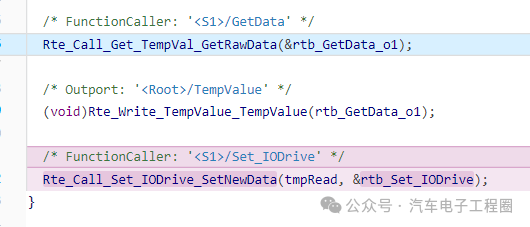 4 ConclusionThis article briefly introduced the concept of the AUTOSAR CS interface in Simulink, as well as how to configure and generate code in one scenario. More situations can be determined based on your project. This is also the first time manually configuring the AUTOSAR CS interface, and compared to automatic generation experience, some new discoveries have been made. Future articles will bring more discussions, and everyone is welcome to actively comment and master more about the use of AUTOSAR interfaces in Simulink.Creating is not easy, please like, follow, and save!! ( Qian Yixing changed name Automotive Electronics Engineering Circle) Automotive R&D group chat, interested friends please add the group owner: prOmiseyes, note: company + position to join the group. Limited to automotive practitioners.
The series of articles on ECU application layer software models is continuously updated, teaching you application layer development from scratch:
- Example 1 of building ECU application layer software model (qq.com)
- How to automatically generate code for ECU application layer software model 2 (qq.com)
- How to run ECU application layer software periodically 3 (qq.com)
- Code generation configuration related to ECU application layer software model and hardware 4 (qq.com)
- Data Dictionary DD in ECU application layer software model 5 (qq.com)
- Data Dictionary Storage Class in ECU application layer software model 6 (qq.com)
- Fixed-point implementation in ECU application layer software model 7 (qq.com)
- Five fixed-point implementation methods in ECU application software model 8 (qq.com)
- Custom storage class in ECU application layer software model 9 (qq.com)
- Summary of model generation code in ECU application layer software model 10 (qq.com)
- CAN reception in ECU application layer software model 11 (qq.com)
- Data stream reception of CAN message in ECU application layer software model 12
- How to leverage AI in ECU software development? Application of Kimi in MBD development environment 13
-
Unit test coverage CC, DC, and MCDC detailed explanation in ECU application layer software model 14
-
Application and principles of calibration and observation quantities in ECU application layer model development 15
-
Use of for loop in ECU application layer model development 16
- Use of if-else in ECU application layer model development 17
- Initialization function in ECU application layer model development 18
-
Counter in ECU application layer model development 19
-
Basics of Assignment module in ECU application layer model development 20
-
Application of Delay module in ECU application layer model development 21
-
ECU application layer model development If-else VS switch-case 22
-
Simulink.Signal in ECU application layer model development 23
-
Data overflow handling in ECU application layer model development 24
-
Disasters caused by Delay in ECU application layer model development 25
-
Usage of Tapped Delay in ECU application layer model development 26
-
First-order low-pass filtering in ECU application layer model development 27
- Simulink.Parameter in ECU application layer model development 28
- Discussion on modeling methods in ECU application layer software model development 29
- Feedback + PI control in ECU application layer software model development 30
- Using Simulink to deploy AUTOSAR in ECU application layer software model development 31
-
Using Simulink to create AUTOSAR SR interface in ECU application layer software model development 32