RS-485 Network
The PPI, MPI, and PROFIBUS-DP protocols supported by the S7-200 system are typically based on RS-485 electrical networks as their hardware foundation. The RS-485 serial communication standard employs balanced signal transmission, also known as differential mode. This balanced transmission method effectively suppresses interference during transmission. Balanced transmission uses a pair of wires to transmit signals based on the voltage difference between the two wires. These two wires are designated as A (TxD/RxD-) and B (TxD/RxD+). When the voltage of B is higher than that of A, it is considered to transmit a logic “high” level; when the voltage of B is lower than that of A, it is considered to transmit a logic “low” level signal. The effective differential voltage range is quite broad, ranging from a few hundred millivolts to nearly ten volts. The RS-485 communication port can achieve high communication rates, long communication distances, and allow multiple ports to be connected in parallel.
The common-mode rejection voltage of the S7-200 CPU communication port is 12V. Therefore, for this type of non-isolated RS-485 port, it is crucial to ensure that the signal grounds between communication ports are at the same potential, and it is best to connect them together (not necessarily to ground).
The RS-485 ports in the S7-200 system are half-duplex, meaning they cannot send and receive signals simultaneously. In the S7-200 system, by selecting appropriate communication devices, baud rates can range from 1200 to 12M, with a single segment distance of 1000m and up to 32 stations in a communication network. Through repeaters, the RS-485 electrical network can also extend communication distances and increase communication stations. For more details, please refer to the dedicated chapter on communication in the “S7-200 System Manual.” Although common RS-485 communication devices are generally consistent in electrical performance, their physical interfaces vary widely, with no unified specifications.
1.1 RS-485 Communication in the S7-200 System
In the S7-200 system, the communication port on the CPU (programming port) and the communication port on the EM277 module both comply with the RS-485 electrical standard. However, they also have differences:
·The communication port on the S7-200 CPU is non-isolated, with a maximum communication rate of 187.5K baud.
·The communication port on the EM277 is isolated, with a maximum communication rate of 12M, and it is rate adaptive.
The following three protocols can all be implemented on the hardware basis of RS-485:
·PPI (including programming communication, communication between S7-200 CPUs, and communication between S7-200 CPU and HMI, etc.)
·MPI (communication between S7-200 CPU and S7-300/400 CPUs, communication between S7-200 CPU and HMI, communication between EM277 and HMI, etc.)
·PROFIBUS-DP (communication between EM277 and other PROFIBUS-DP masters)
Therefore, when examining the communication of the above electrical networks, we should note that they are all constrained by the electrical foundation of the RS-485 network.
The network hardware used in the above networks is fundamentally the same.
Hardware Composition of RS-485 Network
In the S7-200 system, whether forming a PPI, MPI, or PROFIBUS-DP network, or a Modbus RTU network, the main components used are the same:
·PROFIBUS cable: There are various cable models, among which the most basic is the PROFIBUS FC (Fast Connect) Standard cable (Order No. 6XV1 830-0EH10).
·PROFIBUS network connectors: There are various forms of network connectors, such as different exit angles, etc.
5.1 Connecting Network Connectors
A. Cable and Stripper. Using FC technology does not require stripping exposed copper wire.

Figure 1. PROFIBUS cable with one end stripped and quick stripper (FCS, Order No. 6GK1905-6AA00).
B. Open the PROFIBUS network connector. First, open the cable tension release block, then lift the core wire lock.
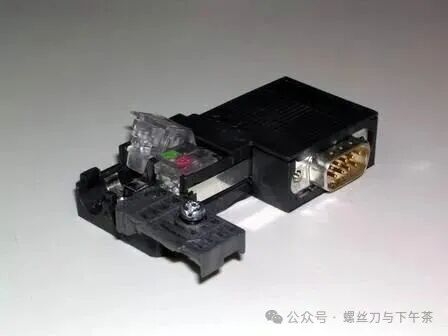
Figure 2. Opened PROFIBUS connector
C. Remove the protective layer from the outer core of the PROFIBUS cable, insert the core wire according to the corresponding color markings into the core wire lock, and then press down the lock block firmly to ensure contact of the internal conductors. It is important to ensure that the stripped shielding layer of the cable contacts the shielding connection pressure piece.
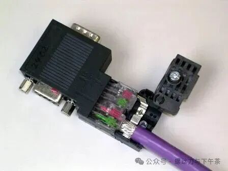
Figure 3. Inserting the cable
D. Reset the cable pressure block, tighten the screws, and eliminate the impact of external tension on the internal connection.
2. Network Connectors
Network connectors are mainly divided into two types: with and without programming ports. Connectors without programming ports are used for general networking, while connectors with programming ports can still provide a programming connection port for programming or connecting to HMI while networking.
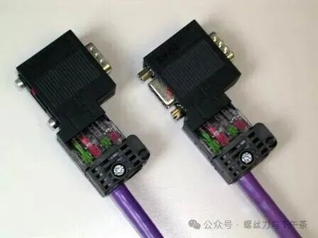
Figure 4. On the left is a network connector without a programming port (Order No.: 6ES7 972-0BA52-0XA0) and on the right is a network connector with a programming port (Order No.: 6ES7 972-0BB52-0XA0).
3. Linear Network Structure
Connect network plugs through PROFIBUS cables to form a bus-type network structure.
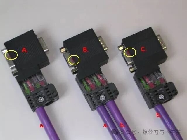
Figure 5. Bus-type network connection
In the above figure, network connectors A, B, and C are plugged into the communication ports of three communication stations; cable a connects plugs A and B, and cable b connects plugs B and C. The linear structure can be extended in this manner.
Note the setting of the “termination resistor” switch within the circle. The plug at the network terminal must have its termination resistor switch set to “ON”; the plugs at intermediate stations should have their termination resistor switches set to “OFF”.
4. Termination Resistors and Bias Resistors
A proper RS-485 network uses termination resistors and bias resistors. Termination and bias resistors can be omitted when the network connection lines are very short, temporary, or for laboratory testing.
Termination Resistor: A resistor connected in parallel across a pair of communication lines at the two ends of a linear network (the two most distant communication ports). According to transmission line theory, termination resistors can absorb reflected waves on the network, effectively enhancing signal strength. The value of the two termination resistors in parallel should be approximately equal to the characteristic impedance of the transmission line at the communication frequency. Bias Resistor: Bias resistors are used to ensure the relative relationship of signals A and B under complex electrical conditions, ensuring the reliability of “0” and “1” signals.