The RS-232 standard was jointly established by the Electronic Industries Association (EIA) of the United States and companies like Bell Systems in 1970, originally aimed at standardizing serial binary data exchange between Data Terminal Equipment (DTE) (such as computers) and Data Communication Equipment (DCE) (such as modems). It employs serial communication, transmitting data one bit at a time in sequence.
 ⚡ Electrical Characteristics: Different “Logic”RS-232 uses negative logic levels:
- Logic “1”: -3V to -15V
- Logic “0”: +3V to +15V
This differs from the common TTL levels inside computers (0V represents logic “0”, +5V represents logic “1”), thus often requiring level conversion chips (like MAX232) for conversion.🔩 Mechanical Interface: Common Connectors
The RS-232 interface primarily uses DB-type connectors:
-
DB-25: The early standard specified 25 signal lines.
-
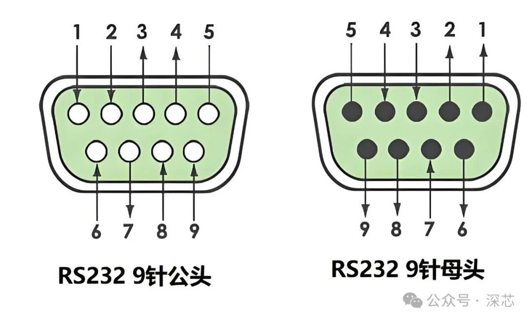
DB-9: The IBM PC simplified it to a 9-pin DB-9 connector, which became the de facto standard. This is commonly found on desktop COM ports.
In practical applications, especially in industrial control, basic communication can often be achieved using just three lines: RXD (Receive Data), TXD (Transmit Data), and GND (Signal Ground).
Below is the common pin definition for the DB-9 connector (female):
| Pin Number | Signal Abbreviation | Signal Full Name | Function Description |
|---|---|---|---|
| 1 | DCD | Data Carrier Detect | Data carrier detection, usually indicated by the modem to inform the computer whether the line is normal. |
| 2 | RXD | Received Data | Receive Data, data input line. |
| 3 | TXD | Transmitted Data | Transmit Data, data output line. |
| 4 | DTR | Data Terminal Ready | Data terminal ready, informs external devices that the computer is ready. |
| 5 | GND | Signal Ground | Signal Ground, provides reference level. |
| 6 | DSR | Data Set Ready | Data device ready, informs the computer that the external device (like a modem) is ready. |
| 7 | RTS | Request To Send | Request to send, the computer indicates its desire to send data to the external device through this signal. |
| 8 | CTS | Clear To Send | Clear to send, the external device responds to RTS with this signal, indicating that the computer is allowed to send. |
| 9 | RI | Ring Indicator | Ring indicator, the modem uses this signal to notify the computer of an incoming call. |
💡 In practical applications, the simplest three-wire connection only requires connecting 2 (RXD), 3 (TXD), and 5 (GND). Other pins are mainly used in cases where hardware flow control or status detection is needed, especially when communicating with traditional devices like modems.
🧭 In-depth Understanding of Hardware Flow Control (RTS/CTS)
This is the most important and commonly used function aside from the basic transmit, receive, and ground lines. It works in conjunction with the RTS and CTS pins to prevent data loss, especially when the receiving end cannot keep up with the sending end’s speed.
Workflow: Before the computer (DTE) sends data, it first sets the RTS signal high (request to send). If the modem (DCE) is ready to receive, it sets the CTS signal high (clear to send) in response. The computer only begins sending data through the TXD line after detecting that CTS is valid. If the modem cannot process (for example, if the buffer is full), it will not set CTS high, and the computer will wait.
📊 Communication Characteristics and Parameters
RS-232 communication has the following main characteristics:
-
Transmission Distance: The standard transmission distance generally does not exceed 15 meters (about 50 feet). Beyond this distance, signal quality may degrade, requiring devices like modems to extend the range.
-
Transmission Rate: The standard rate range is quite broad, from 50 b/s to 19200 b/s, and under specific conditions, even higher rates (like 115.2kbps) can be achieved.
-
Operating Mode: Supports full-duplex communication (can send and receive data simultaneously).
-
Connection Method: Primarily used for point-to-point communication.
-
Scalability: It does not support bus-type networking by itself. To connect multiple devices, it usually requires multiple serial ports or external devices (like serial servers).
🔄 Wiring Method: Direct or Crossed?
RS-232 devices are classified as DTE (Data Terminal Equipment, such as computers) and DCE (Data Communication Equipment, such as modems). They communicate by crossing the transmit (TXD) and receive (RXD) pins:
-
When connecting a DTE (computer) to a DCE (modem), a straight-through cable is generally used (2 to 2, 3 to 3, 5 to 5).
-
When two DTE devices (like two computers) are directly connected, a crossover cable is needed (2 to 3, 3 to 2, 5 to 5) to ensure one party’s transmitter connects to the other party’s receiver.