Previously, we wrote an article specifically about oscilloscope probes, and recently a friend asked for a detailed introduction to “differential probes”. Today, I will organize the information.Definition of Differential Probes
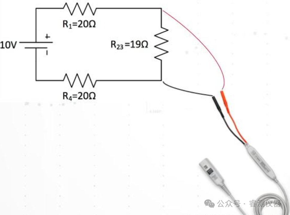
A differential probe is an electronic measurement tool used foraccurately measuring the voltage difference (differential signal) between two test points rather than the voltage at a single point relative to ground. Its core function is to suppress common-mode noise, amplifying only the differential signal, making it suitable for high-noise environments or scenarios requiring isolated measurements.The main difference between differential probes and regular probes lies in their working principles. Differential probes utilize electronic principles to measure the difference in voltage, while regular probes measure voltage in a circuit by directly connecting the test resistance to the circuit. Due to the different processing and calculation methods, differential probes provide more accurate measurement values, while regular probes perform better in low-frequency circuits and signal processing.
 Background of Differential Probes
-
Demand-Driven:
-
Common-Mode Interference Resistance: In complex circuits, single-ended probes are easily affected by ground noise (such as power interference, ground loops), leading to measurement errors.
-
Safety Isolation: When measuring high-voltage or floating ground systems (such as switch power supplies, motor drives), traditional probes may pose a short-circuit risk.
-
Popularity of Differential Signals: Modern high-speed digital communications (such as USB, CAN bus) and power electronics (such as inverters) widely adopt differential transmission, requiring specialized tools for capture.
-
Technical Advantages:
-
High Common-Mode Rejection Ratio (CMRR), typically exceeding 60dB, effectively filtering out common-mode noise.

-
Supports high bandwidth (GHz level) and high voltage (thousands of volts) measurements.
Application Scenarios for Differential Probes
| Scenario Type | Typical Applications | Example Fields |
|---|---|---|
| High-Speed Differential Signals | USB 3.0, HDMI, Ethernet, PCIe interface signal integrity testing | Communication devices, computer hardware |
| High Common-Mode Voltage Systems | Switching node measurements of motor drivers, inverters, power modules | Industrial control, new energy (photovoltaics/electric vehicles) |
| Floating/Isolated Systems | Medical devices (such as ECG), primary side signals of isolated power supplies | Medical electronics, power electronics |
| Low-Level Signals | Weak differential signals from sensor outputs (such as strain gauges, thermocouples) | Instrumentation, automation control |
Types of Differential Probes
-
Classified by Working Principle and Structure
| Type | Features | Applicable Scenarios |
|---|---|---|
| Active Differential Probes | – Built-in amplifier, high bandwidth (up to several GHz)– Low input capacitance (<1pF), low circuit loading | High-speed digital signals, RF circuits |
| Passive Differential Probes | – No power supply, simple structure– Lower bandwidth (usually <100MHz), low cost | Low-frequency differential signals, educational experiments |
| Isolated Differential Probes | – Electrical isolation between input and output (withstanding several kV)– High safety, supports floating measurements | High-voltage systems (such as IGBT driver circuits) |
-
Classified by Voltage Range
-
Low-Voltage Differential Probes: Measurement range of ± tens of volts, suitable for digital circuits, sensor signals.
-
High-Voltage Differential Probes: Measurement range of ± thousands of volts, used for power electronics, motor drives.
-
Classified by Bandwidth
-
Low-Frequency Differential Probes: Bandwidth <100MHz, suitable for power noise, audio signal analysis.
-
High-Frequency Differential Probes: Bandwidth ≥1GHz, used for high-speed serial buses, RF signal testing.
Key Parameters for Selecting Differential Probes
-
Bandwidth: Should be greater than 5 times the highest frequency of the signal (for example, for measuring a 100MHz signal, select a probe with ≥500MHz).
-
Common-Mode Rejection Ratio (CMRR): The higher, the better (for example, 60dB@1MHz indicates a 1000-fold attenuation of common-mode signals).
-
Input Impedance: High impedance (≥1MΩ) reduces the impact on the measured circuit.
-
Maximum Differential Voltage: Ensure the probe’s range covers the amplitude of the measured signal.
Precautions When Using Differential Probes
- Measurement Voltage Range
The vast majority of high-bandwidth active differential probes cannot support high-voltage testing. For example, the 1169 series probe amplifier has a bandwidth of up to 12GHz, a DC bias of ±16V, and a maximum voltage of ±30V. During testing, if the amplitude of the measured signal exceeds the maximum voltage range, it may damage the probe.
2. Connection Between Probe and Oscilloscope
Common high-bandwidth active differential probes can only connect to the gold-plated BNC interface of the oscilloscope. When connecting, the probe amplifier should be inserted vertically into the oscilloscope input interface. Once inserted, the lock will automatically close. To remove it, the lock must be released first, and then it should be pulled out vertically.
3. Connection of Probe Front-End
Depending on the different measurement scenarios of customers, different front-ends usually need to be selected. Tektronix provides a rich variety of front-end options such as soldering, slots, sleeves, SMA, etc. The front-end can be inserted vertically into the amplifier’s connection end without the need for rotation, bending, or squeezing. The differential front-end has no positive or negative distinction, but the amplifier does, so the single-ended probe front-end needs to be inserted into the positive end of the amplifier.
4. Operating Temperature Range
Due to the segmented design, the amplifier and front-end can be separated, allowing the front-end to have a wider temperature range. If considering high and low-temperature testing, it can be extended to -55℃ to +150℃ by using extended cables with different front-ends. However, the amplifier can only operate at room temperature.
5. Fixing Methods and Usage Tips for Soldering Probes
a. Since the soldering front-end is very thin and fragile (due to material properties and cost-performance ratio), to prevent detachment caused by external force, it is usually necessary to fix the front-end of our amplifier and the amplifier itself. Non-conductive double-sided tape or a small amount of low-temperature hot glue can be considered, but strong glue should be avoided. When using low-temperature hot glue, be careful not to let the hot glue contact the front-end to avoid damage. Additionally, the nylon adhesive disc that comes with the amplifier can be used to fix the amplifier.
b. The soldering probe front-end is usually equipped with replaceable matching soldering resistors, which can be replaced when the resistor is damaged or falls off. However, care should be taken not to cause the front-end solder pad to fall off during the soldering process; if it falls off, the front-end can only be replaced.
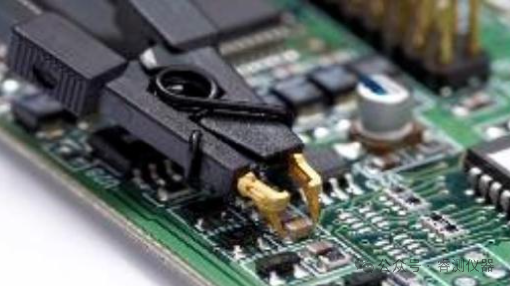
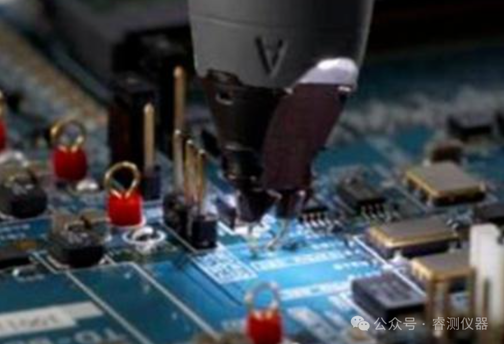
c. When using differential probes, be careful to protect the front-end probes. Do not use the probes to scrape the green oil, oxide layer, or anti-corrosion paint on the circuit board, as this may damage the probes. The probes should be as vertical as possible to the measured point, and can be pressed lightly to ensure a reliable connection. Note that when using browser-type front-ends, the spacing of the probes should be adjusted using the knob, and should not be directly pulled apart by hand.

Scan the QR Code

Follow Us
Business|Instrument Rental, Sales, Maintenance
Phone|Yang 13912605605
-
Email|[email protected]
Address|Suzhou, Shanghai, Shenzhen, Nanjing