
Application of Real-Time Oscilloscopes in New Generation Optical Interface Time Domain Testing
Introduction: When it comes to time domain testing of optical interface metrics, engineers often mention the sampling oscilloscope. This is because sampling oscilloscopes have unparalleled advantages in signal integrity: high bandwidth, low noise, and minimal quantization error (high vertical resolution). However, the downside is the need for synchronized triggering clocks, leading optical engineers to gradually forget about real-time oscilloscopes.
Challenges: For a long time, engineers conducting optical interface tests (especially optical module tests) have not worried about synchronized triggering clocks, either bringing them from a pattern generator or using a clock recovery unit to recover the clock from the measured signal. The former is highly cost-effective for production testing, while the latter is often used in R&D, pursuing ultimate testing results. However, as the speed of optical interfaces continues to increase, especially for multi-channel optical interfaces above 25GBps, each signal path has added re-timer units. This means that different signal paths within the same optical interface (optical module) actually come from different sources. In other words, the synchronized clock and signal from the pattern generator may no longer be synchronized, which is particularly evident in current PAM4 optical module testing. Actual comparative tests have shown that using a clock recovery unit for testing yields better results than using a pattern generator synchronized clock as a trigger. However, when engineers need to conduct higher-speed tests, the cost of clock recovery devices can be very high, significantly increasing testing costs.
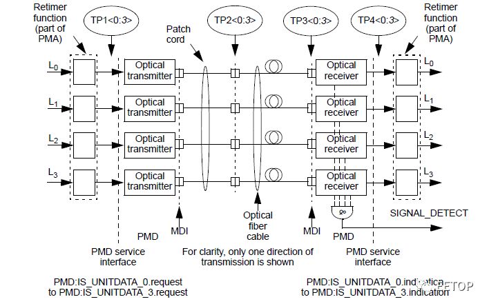
Figure 1: A typical multi-channel 25GBps optical transceiver, each path has a re-timer
New Attempts: As is well known, the inconvenience of sampling oscilloscopes is the inherent advantage of real-time oscilloscopes: when capturing signals, real-time oscilloscopes use internal time bases, eliminating the need for external synchronized triggering clocks. However, real-time oscilloscopes have always been perceived as having low bandwidth, high noise, and large quantization errors. Moreover, they only support electrical inputs. Fortunately, with continuous technological advancements, real-time oscilloscopes have undergone tremendous changes; bandwidth is no longer an issue, noise is decreasing, and most importantly, high-bandwidth optical probes have emerged to complement real-time oscilloscopes. Thus, engineers can attempt to use high-performance real-time oscilloscopes for testing the new generation of optical interfaces.
The combination of real-time oscilloscopes and optical probes completely eliminates the need to consider external synchronized triggering signals, allowing for direct signal capture. Clock recovery is implemented via software, with phase-locked loop bandwidth being more precise and flexible (in R&D scenarios, the phase-locked loop bandwidth can be set arbitrarily). Additionally, the testing connection is extremely simple, requiring only a single optical fiber without any cables.
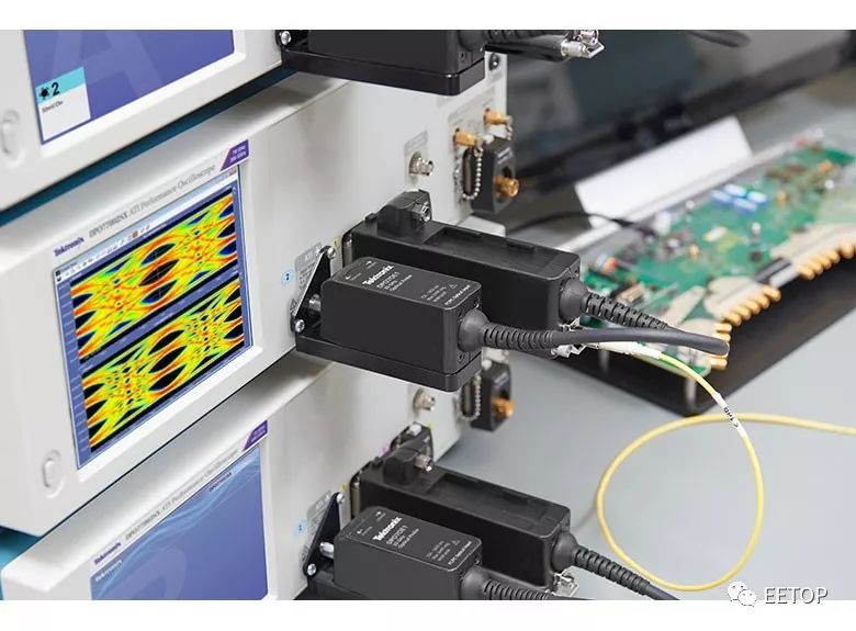 Figure 2: A new real-time optical interface testing solution
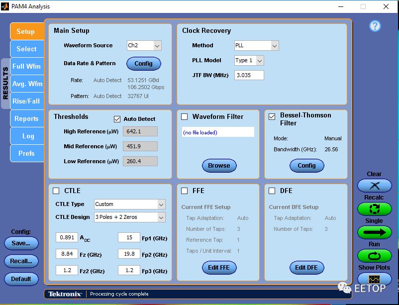 Figure 3: The simple configuration interface of the real-time analysis software
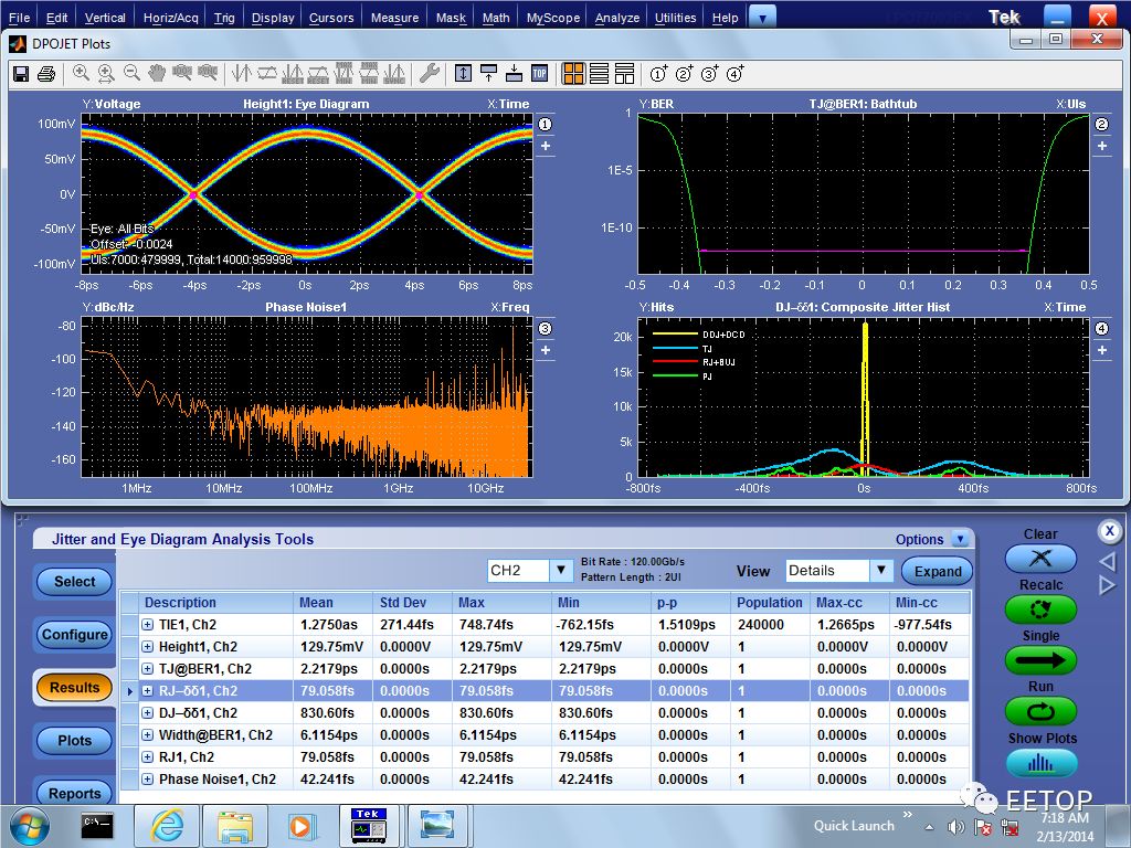
Comprehensive support for testing projects: In addition to supporting the consistency testing projects required by IEEE, it also supports numerous R&D testing projects such as jitter, error localization, and bit error rate estimation.
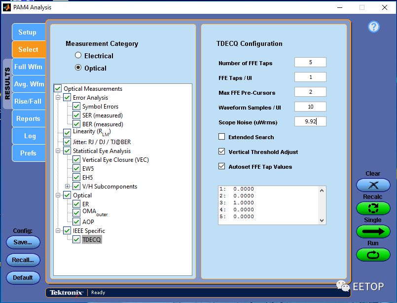
Figure 4: In addition to the consistency testing projects required by IEEE, it also supports numerous R&D analysis projects
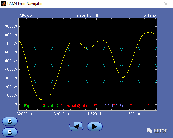
Figure 5: Bit error detection and localization
Comparison of Test Results: The test results are very consistent.
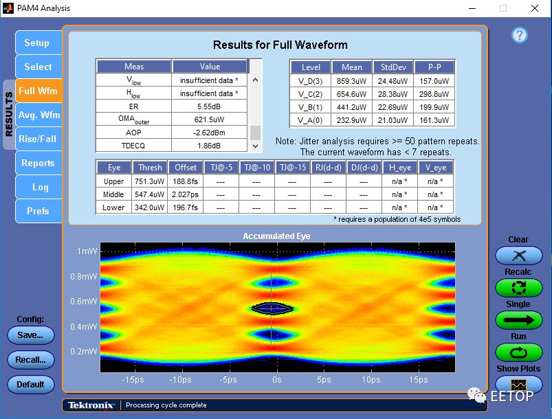
Figure 6: Test results of 53GBd PAM4 using a real-time oscilloscope
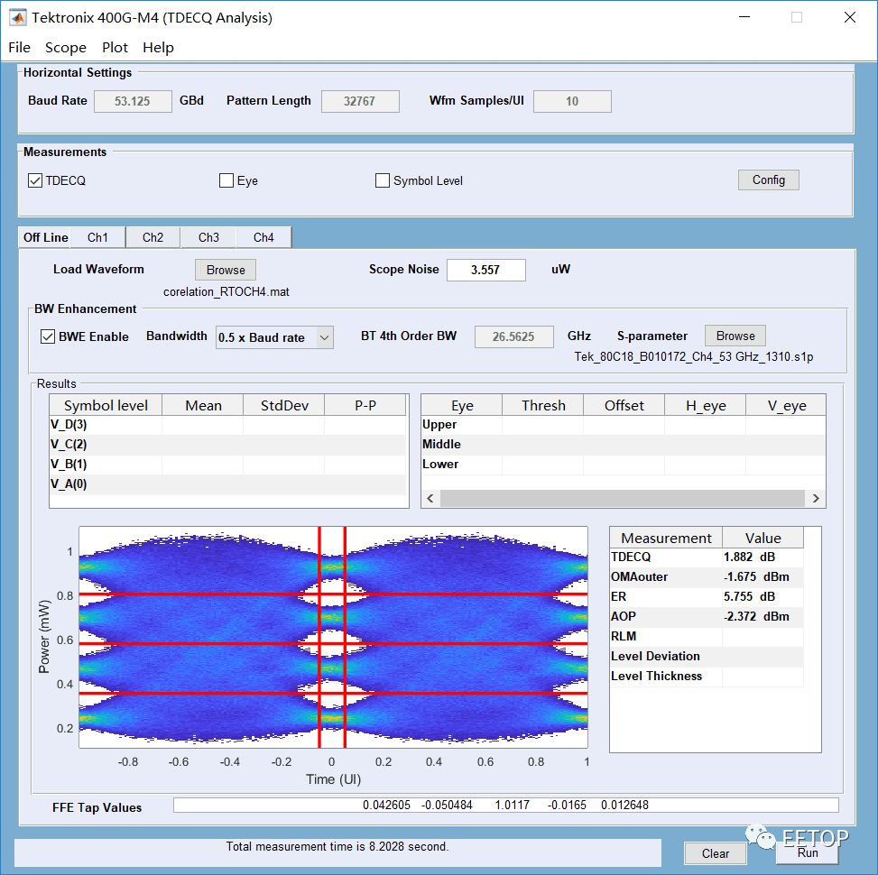
Figure 7: Test results of PAM4 using a sampling oscilloscope
Discussion & Conclusion: The real-time oscilloscope solution has emerged, demonstrating positive results in terms of testing connection convenience and the relevance of test results.Real-Time vs Sampling: Which is Better?
|
Real-Time Oscilloscope Solution |
Sampling Oscilloscope Solution |
|
|
Waveform Capture Speed |
Fast, millisecond level |
Slow, second level |
|
External Trigger Clock |
Not required |
Required |
|
Clock Recovery Phase-Locked Loop Bandwidth |
Software implementation, flexible settings |
Hardware CDR, limited setting range |
|
Vertical Axis Resolution |
8bit |
14bit |
|
Low Noise |
Somewhat higher |
Low |
|
Trigger System Jitter Floor Noise |
100fs level |
400fs level |
Real-Time vs Sampling: Which test results are more realistic? Or which better reflects the reception effect of a real receiver? This is a question of great concern to every engineer.
|
Actual Receiver |
Real-Time Oscilloscope |
Sampling Oscilloscope |
|
|
Signal Acquisition |
Continuous |
Continuous |
Intermittent |
|
Clock Recovery |
Hardware |
Software |
Hardware |
|
Signal Acquisition |
Single |
Single |
Repeated |
|
Sensitivity to Amplitude Drift |
Insensitive |
Insensitive |
Sensitive |
|
Sensitivity to Low-Frequency Jitter |
Insensitive |
Insensitive |
Insensitive |
|
Sensitivity to High-Frequency Jitter |
Sensitive |
Sensitive |
Sensitive |
Those who find the real-time solution unreliable are generally concerned about the vertical resolution and floor noise of the oscilloscope. Those who believe the real-time solution is good mainly base their opinions on trigger jitter and more precise clock recovery settings. However, Tektronix’s new ATI oscilloscope employs an asynchronous timing interleaving structure, achieving 70 GHz and 200 GS/s (5 ps/sample) real-time acquisition performance. This patented symmetric structure inherently has noise far superior to traditional bandwidth interleaving methods. The DPO70000SX provides the lowest noise, highest fidelity, and maximum performance. The image shows the jitter analysis of a 60 GHz sine wave applied to the ATI input. The results show a clean eye diagram with random jitter RJ <80 fs RMS.
Based on the high performance of the Tektronix ATI oscilloscope, it has been widely used for complex optical modulation analysis, jitter and noise analysis of high-speed serial signaling, and phase and modulation analysis of broadband RF signals. For example, the Changchun Institute of Optics and Fine Mechanics, in collaboration with the Sino-German Green Photonics Research Center, used Tektronix’s ATI oscilloscope for research on “Low-Power VECSEL 200+ Gbps Optical Interconnects.”
The following image is from Gunter Larisch’s paper “Energy-efficient VCSELs for 200+ Gb/s optical interconnects”
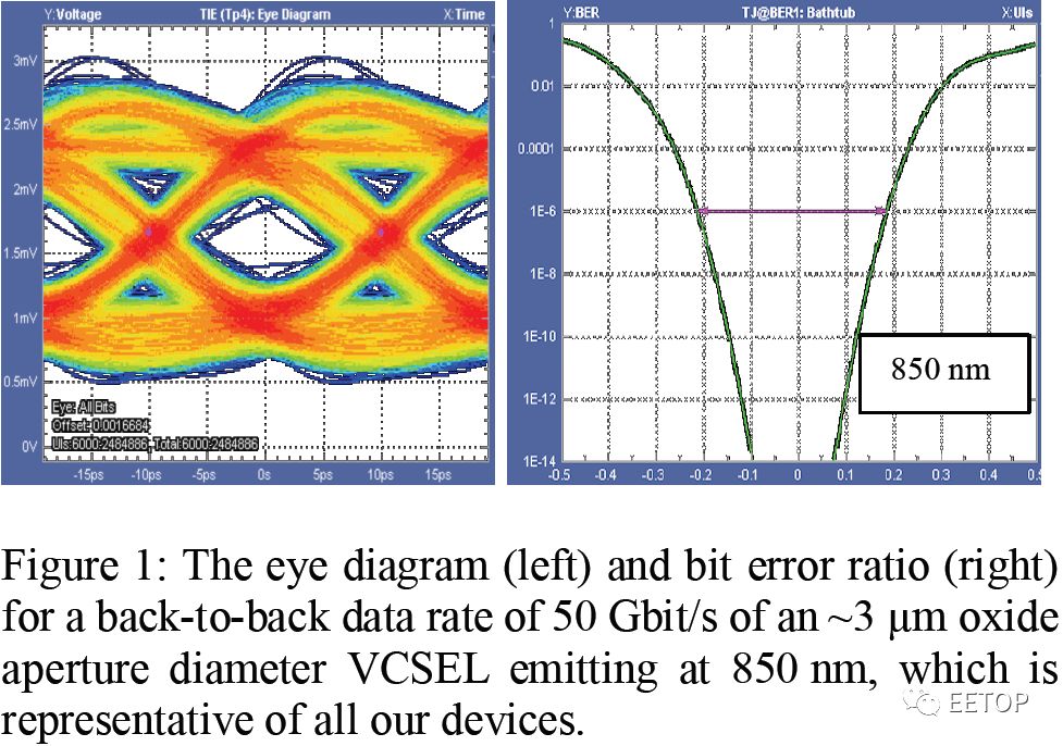 Figure 8: Real-time oscilloscope aiding research on low-cost, low-power 50GBps laser devices
The real-time oscilloscope is used for research on multimode low-cost, low-power laser devices. The DUT in the image operates at a rate of 50GBps and has transmitted through 2 meters of OM5 multimode optical fiber. Excellent signal integrity and flexible, comprehensive jitter analysis capabilities are the reasons Dr. Larisch chose the real-time oscilloscope.
Friendly Reminder

Thank you for reading the article from EETOP. If you liked this article, please share it with your friends. For more information, please follow me.
Click to Follow