
How to correctly use instruments and meters is a necessary requirement for every engineer, especially for oscilloscopes. Many people do not pay attention to isolation and other restrictions, leading to incidents such as exploding probes. So what unsafe operations are there when using oscilloscopes?
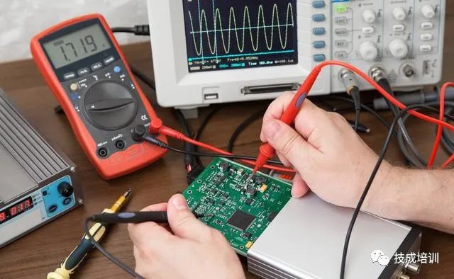
Some engineers have a habit: when measuring high-voltage signals, they habitually disconnect the protective ground of the power plug and use ordinary passive probes to perform floating measurements of high voltage. In fact, this practice is still hazardous.
Common Phenomena Example: Feeling electric shock when touching the oscilloscope case
Check: 1. Is the oscilloscope power ground manually disconnected or poorly connected? 2. Change the power strip; 3. The building’s ground is not properly connected.
Reason: The Y capacitor is connected between the hot line and ground, and between the neutral line and ground, as shown in Figure 1. It primarily serves to filter and protect, and suppress common mode interference. It is a safety capacitor. If the capacitor fails, it will not cause electric shock and will not endanger personal safety. When the protective ground of the power plug is disconnected, 220V voltage is divided by the Y capacitor, and 110V voltage is directly applied to the metal case of the oscilloscope. When a person touches the live area, it can cause an electric shock sensation like being pricked by a needle, which, although not life-threatening, is still a dangerous operation.
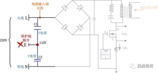
▲Figure 1 Power Circuit Diagram
Common Phenomena Example: Tripping / Burnt circuit board / Burnt oscilloscope or probe
Check: 1. Is the ground of the measured signal common with the oscilloscope’s calibration signal ground? 2. When measuring AC mains, is it measured directly with a single passive probe?
Before analyzing the reasons, it is important to understand what AC mains is and the composition of the power supply circuit. In China, the specification for AC mains (residential electricity) is 220V @ 50Hz. The power supply circuit consists of the hot line, neutral line, and ground line, as shown in Figure 2.
l Hot Line (L): Also known as phase line, provided by the power station or substation, voltage 220V, dangerous if touched;
l Neutral Line (N): Provides a return loop for the hot line, grounded at the power station or substation; since it is grounded at a distance, the potential at the user end in residential buildings may not be zero and may carry weak current, but is relatively safe;
Ground Line (E): Zero potential reference point, grounded at the user end in residential buildings, zero voltage, absolutely safe.
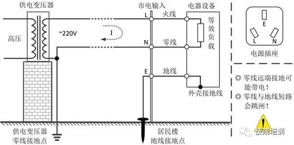
▲Figure 2 Relationship of Three Lines
Reason: In power system testing, it is often required to measure the relative voltage difference between the hot lines in three-phase power supply or between the hot line and neutral line. However, all channels of ordinary digital oscilloscopes are grounded and not isolated from each other. All signals applied to the oscilloscope and provided by the oscilloscope have a common connection point, which is usually the oscilloscope case connected to the ground wire of the AC power supply device. If a single-ended probe is used for measurement, then the ground wire of the single-ended probe will be directly connected to the power line, resulting in a short circuit.
1. Self-checking “Ground” Before Wiring
How can we determine if the ground on the probe can be directly connected to the ground of the measured board? It’s simple, three steps to achieve self-check:
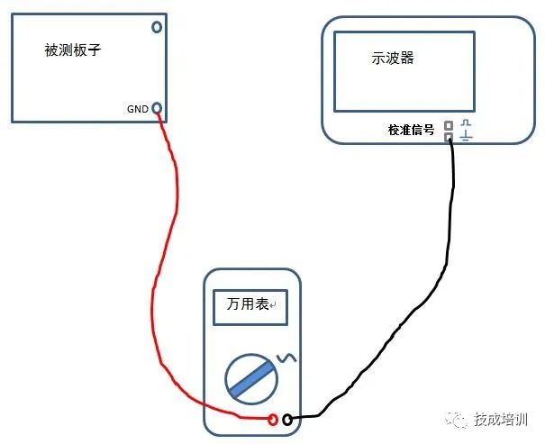
Tools needed: Measured board, multimeter, oscilloscope
(1) Preparation: Turn on the multimeter, select the maximum AC range;
(2) Wiring: Connect the oscilloscope and the measured board to power, but do not turn on yet; connect one end of the multimeter probe to the oscilloscope’s calibration signal ground, and the other end to the measured board’s ground. A simple wiring diagram is shown in Figure 3;
(3) Measurement: Power on both devices and measure the AC value.
If the measured value is not zero, it indicates that there is a voltage difference between the measured board and the oscilloscope ground, as illustrated in Figure 4. Therefore, do not directly connect the ground clip of a single passive probe to the ground of the measured board.
▲Figure 3 Voltage Difference Wiring Diagram
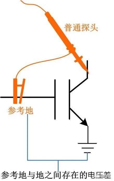
▲Figure 4 Do Not Directly Connect Two “Grounds” When There Is Voltage Difference
1. “A-B” Pseudo Differential Measurement of AC Mains
When using ordinary passive probes to measure AC mains with the “A-B” method, both probe grounds should be connected to the power ground, one probe tip (positive terminal) should connect to the neutral line, and the other probe tip (positive terminal) should connect to the hot line (as shown in Figure 5 left). The measurement difference of the two channels will be the AC mains waveform.
However, this method may have measurement errors. If the signal is a low-frequency signal, and the signal amplitude is large enough to exceed any concerning noise, this method can be used.
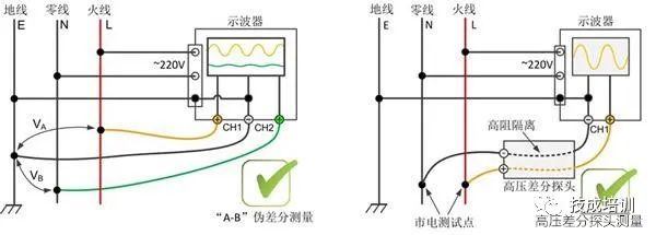
▲Figure 5 Recommended Wiring Diagram for Measuring AC Mains
1. Best Measurement Method: Use High Voltage Differential Probes
Using high voltage differential probes for measurement is both safe and ensures accurate measurement results. The best solution for floating measurements and measuring AC mains (wiring diagram as shown in Figure 5 right) is to use differential probes with a high common-mode rejection ratio. Since there is no grounding issue with both input terminals, the differential operation of the two input signals is completed in the probe’s front-end amplifier, and the signal transmitted to the oscilloscope channel is the differential voltage, allowing for safe measurements.
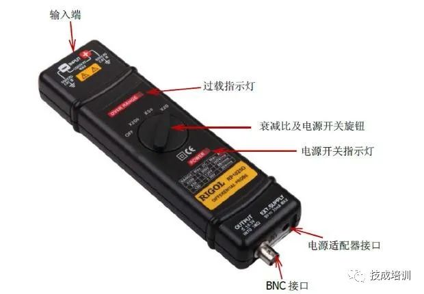
▲Figure 6 High Voltage Differential Probe
Although high voltage differential probes are more expensive than ordinary passive probes, they ensure more accurate and safer measurement results when measuring high voltage signals. It is recommended to use them for AC mains and floating measurements.
Source: Internet
Recommended Reading

Can You Learn PLC on Your Own?
Click to view
Get Beginner PLC Learning Materials

Revealing the Real Salary of Electricians, How Low Is It?
Click to view
Get Electrician Promotion and Salary Increase Secrets