MODBUS RTU Communication Settings for Mitsubishi FX5
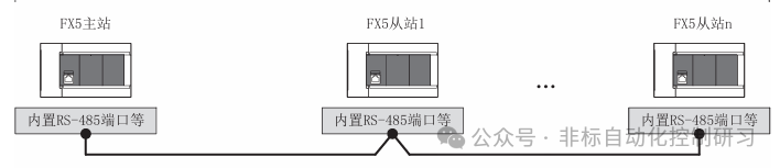
MODBUS RTU communication falls under the category of serial communication. The MODBUS serial communication function of the FX5 can control 32 slave devices when using RS-485 communication and can control 1 slave device when using RS-232C communication. In practical applications, the choice between RS-485 and RS-232 mainly depends on the communication distance and functional requirements.
The RS-485 communication distance can reach up to 1200 meters, while the RS-232C communication distance is much shorter, only 15 meters. However, under normal circumstances, a distance of 15 meters is sufficient unless dealing with large equipment. Nevertheless, this transmission distance can be affected by different environmental factors. Therefore, in actual industrial applications, most instrument manufacturers typically standardize communication methods to RS-485, which is commonly used in MODBUS RTU communication.
When using RS-232C:

Regarding station number settings: The master station is generally set to 0, while slave stations can be set within the range of 1-247 (the station number settings may vary by version), but the total number of connectable slave stations is 32.
The general steps for setting up MODBUS serial communication are as follows:
Confirm communication specifications → System configuration and settings → Wiring → Communication settings → Programming.
Here, we choose to use the commonly used RS-485 communication. The system configuration under this communication varies depending on the CPU module settings. Generally, communication is done through communication boards or adapters, but the FX5U CPU has an integrated communication port. As shown in the figure below:
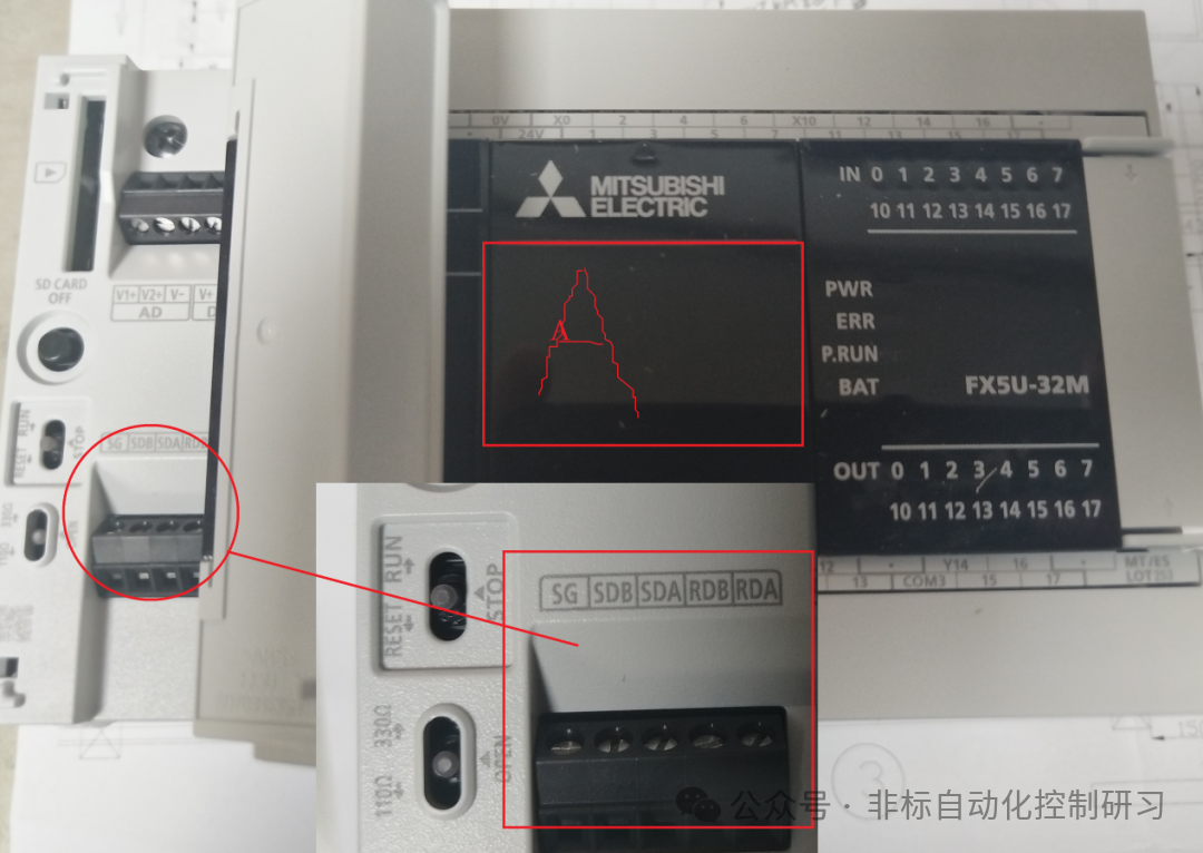
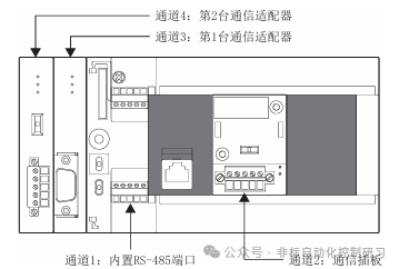
The built-in RS-485 port is Channel 1. The position A in the figure has a port that can communicate through a communication board, which is Channel 2. The other two channels require the FX5-485-BD to be plugged into the front of the main unit in the order closest to the CPU, which are Channel 3 and Channel 4. The allocation of communication channels is fixed and not affected by system configuration. As shown in the figure below:
For the hardware usage and communication distances of each communication channel, please refer to the table below:
|
Communication Port |
Key Points |
Distance |
||
|
Built-in RS-485 Port |
Channel 1 |
Built into the CPU module |
Below 50 meters |
|
|
Communication Board |
FX5-485-BD |
Channel 2 |
Can be built into the CPU module, maintaining the same installation area, compact |
Below 50 meters |
|
FX5-232-BD |
Below 15 meters |
|||
|
Communication Adapter |
FX5-485ADP |
Channels 3 and 4 |
Installed on the left side of the CPU module |
Below 1200 meters |
|
FX5-232ADP |
Below 15 meters |
For CPU models without a built-in RS-485 port, the channel allocation is the same as above, so it can be seen that the maximum number of communication channels is actually 4. In terms of communication specifications, the general settings required include: selecting the communication interface, setting the baud rate, data length, parity, stop bits, etc. The maximum number of writable data for the master station is 125 words or 1968 coils, and the maximum number of readable data is 125 words or 2000 coils. The slave station can only accept one information at a time.
The read and write function codes are shown in the table below:
|
Function Code |
Function Name |
Details |
|
01H |
Coil Read |
Coil read (can be multiple) |
|
02H |
Input Read |
Input read (can be multiple) |
|
03H |
Holding Register Read |
Can be multiple |
|
04H |
Input Register Read |
Can be multiple |
|
05H |
Single Coil Write |
Coil write |
|
06H |
Single Register Write |
Holding register write |
|
0FH |
Multiple Coil Write |
Multiple coil write |
|
10H |
Multiple Register Write |
Multiple holding register write |
Wiring Aspects
Before wiring, it is necessary to select the cable specifications. Using the appropriate cable is essential for maintaining stable communication. RS-232 requires a cable length within 15 meters, complying with RS232 specifications. The key point is for RS-485 communication, which requires twisted shielded cables due to its longer transmission distance, thus having higher specifications as shown in the table below:

There are two wiring methods for RS-485 communication: 1 pair and 2 pair wiring methods. At this time, attention must be paid to the termination resistance. Whether it is the built-in RS-485 port, 485BD, or 485ADP communication modules, they all have termination resistors. As shown in the figure below (the built-in 485 port image from earlier):
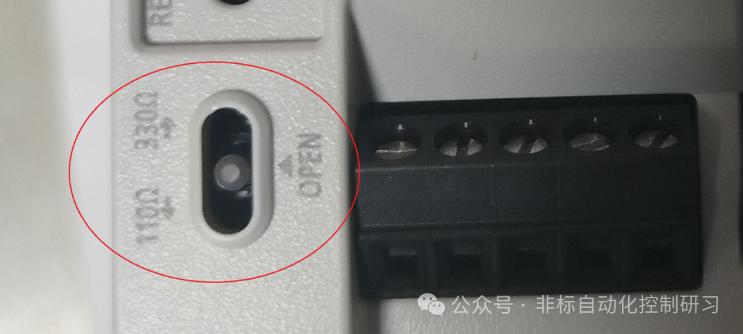
Note: When using the 2 pair wiring method, the termination should be switched to 330Ω, and when using the 1 pair wiring, it should be switched to 110Ω. The communication module also has such a switch. The wiring method is shown in the figure below:


As shown in the figure, termination resistors must be set at both ends.
Next, we can proceed with the actual communication settings.
In the FX5 series PLC, the GX-WORKS3 software is required for setting, programming, and other operations. You need to navigate through the “Navigation Window” → “Parameters” → Module Type → Module Parameters → “485 Serial Port” path to open the display interface, as shown in the figure below:
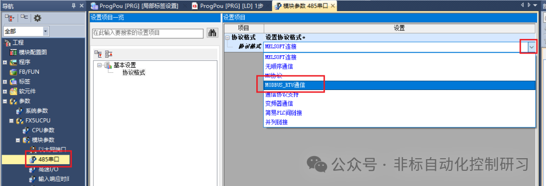
Once MODBUS RTU is selected, detailed parameters can be set, as shown in the figure below:

The detailed settings are exactly as mentioned earlier, as shown in the table below:

Regarding other setting pages that are not mandatory, as shown in the figure below:
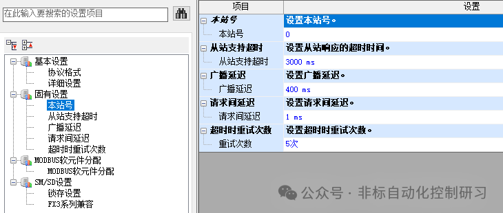
For example, regarding the station number, when the station number setting value is set to “latch” through SM/SD, it can also be changed through special registers. However, for the channel set as the master station (station number 0), even if the special register is set to 1 or above, it will not act as a slave station.
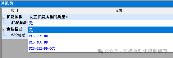
If using an expansion module for communication, you need to make the corresponding selection in the expansion board and then set the protocol format, as shown in the figure below:
Finally, the programming instruction:
Format: ADPRW S1 S2 S3 S4 S5/d1 d2
Parameter Explanation:
S1: Slave station number, range 0-F7H;
S2: Function code, refer to the function code table above;
S3: MODBUS address corresponding to the soft element, range 0000H-FFFFH;
S4: Number of access points, varies by function code;
S5/d1: Starting address of the soft element for reading data;
d2: Communication output status, data type – bit.
Next, I will share programming based on practical cases.