
In many microcontroller circuits, we often see reset circuits, as shown below:
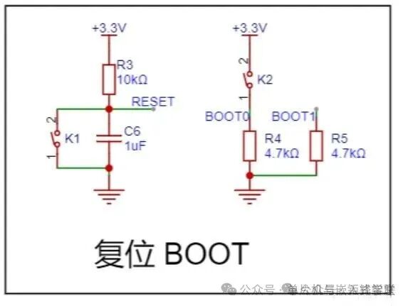
This is the reset circuit in our STM32103C8T6 minimal system board. Let’s study the reset circuit using this example:
A. First, let’s look at the reset circuit on the left:
The RESET signal of the chip is connected to ground through a button and a capacitor in parallel, with a 10k resistor connected to the power supply above.
1. What is a reset?
The function of the microcontroller reset circuit is to set the microcontroller’s state to an initialized state, allowing the microcontroller’s program to execute from the beginning.
During this process, the clock is stable, and various registers and ports are in their initialized states, etc. The goal is to ensure that the microcontroller can stably and correctly execute the program from the start.
There are two types of reset methods for microcontrollers: high-level reset and low-level reset.
The four commonly used reset circuits are as follows:
The first type: Power-on reset circuit:
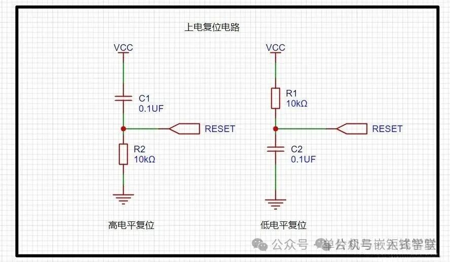
Taking the high-level reset as an example, this circuit uses the charging of the capacitor to achieve reset. When the power is turned on,
the potential at the microcontroller’s reset pin is the same as VCC. As the charging current decreases, the potential at the reset pin gradually drops until the capacitor is fully charged, and the reset pin voltage becomes low.
The values of R and C in the circuit can be calculated using the following formula, where T is the reset time.
T=(1/9)R1C1
Conversely, the calculation formula is: T=9*RC
The second type: Button reset circuit:
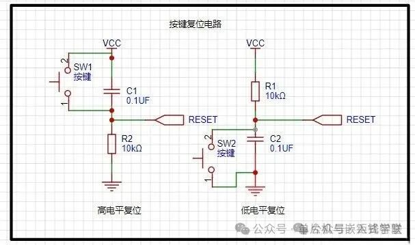
We can generally check the chip’s high and low level reset through the data sheet;
The third type: Button reset circuit with a diode:
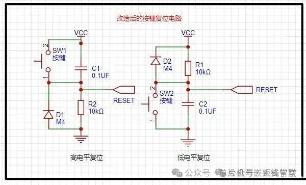
If the second button reset circuit experiences a momentary power interruption due to some interference, the capacitor cannot quickly discharge its charge. When the power is restored, the microcontroller cannot automatically reset, leading to uncontrolled program execution. Momentary power interruptions can cause the program to stop running normally, resulting in program “flying” or entering a “dead loop”.
With this diode, the voltage on the capacitor can be quickly released, ensuring the reset signal is accurate. It also prepares for the next reset quickly.
-
A question arises: the diode is forward-biased towards the power supply; how does it discharge?
Because when VCC is powered off, the voltage across the capacitor cannot change abruptly. For the high-level reset circuit, the upper end becomes 0, causing a negative voltage at the lower end.
At this point, for ground, it becomes high, and the negative voltage becomes low, allowing the voltage to form a loop through ground, the diode, the resistor, and the reset negative voltage to discharge.
For the low-level reset circuit, the high voltage at RRESET discharges through the diode and resistor to ground.
There is a humorous anecdote about resets online:
As long as the power is on, this capacitor will “gradually charge up”. This process is essential as it ensures the CPU correctly “RESETs”.
After the capacitor is fully charged, if we turn off the power switch, where does the charge in the capacitor go?
There are numerous devices connected between VCC and GND, all of which say to it: “Give me that little bit of charge; I can hold on a bit longer.”
The capacitor replies: “No problem, but I have a resistor blocking my path; please wait while I slowly discharge to you.”
Just as the capacitor is about to discharge through that pull-up resistor, the power switch suddenly turns back on.
The CPU starts yelling at the capacitor: “Hey! What happened to that charging process? I still need to reset!”
The capacitor retorts: “Of course! I haven’t discharged the charge from last time, and now the power is back on!”
The CPU panics: “What should I do? I need to reset!”
The capacitor rolls its eyes: “What do you want me to do? Just die!”
The fourth type: Reset circuit using reset chips:
For some very complex circuits, to ensure the chip resets correctly, reset chips must be used to guarantee precise resets.
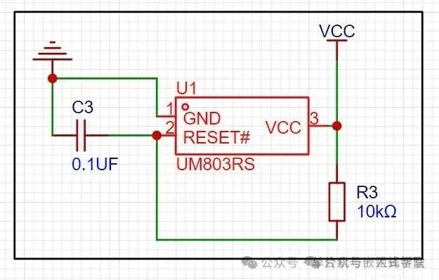
B. Now let’s look at the circuit on the right:
For this circuit, we first need to understand the state of the microcontroller, as follows:
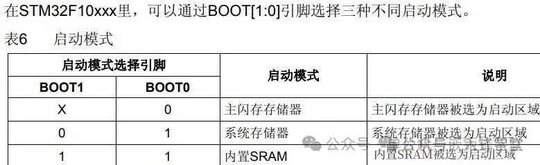
BOOT1 is connected to a pull-down resistor, thus it is low, which means 0, leading to the first and second situations.
When K2 is pressed, BOOT0 is high, 1, starting from the system memory.
When not pressed, it is 0, starting from the main flash memory.
So what are these three modes?
1. Main flash memory is the built-in Flash of the STM32. Generally, when we download programs using JTAG or SWD mode,
it is downloaded here, and upon reboot, the program starts directly from here.
2. System memory starts from the system memory. The program functionality in this mode is set by the manufacturer.
Generally, this startup mode is used less frequently. The system memory is a specific area inside the chip,
where ST pre-installs a BootLoader, which is what we commonly refer to as the ISP program.
This is a ROM that cannot be modified after leaving the factory. Generally, we choose this startup mode to download programs via the serial port,
because the BootLoader provided by the manufacturer includes firmware for serial port program downloading,
allowing us to download programs to the system Flash. However, this downloading method requires the following steps:
Step 1: Set BOOT0 to 1, BOOT1 to 0, and then press the reset button to start the BootLoader from the system memory.Step 2: Finally, with the help of the BootLoader, download the program to Flash via the serial port.
Step 3: After the program is downloaded, BOOT0 must be set to GND, and a manual reset is required so that the STM32 can start from Flash.
3. Built-in SRAM Built-in SRAM, since it is SRAM, naturally has no program storage capability. This mode is generally used for program debugging.
If I only modify a small part of the code, I would need to erase the entire Flash again, which is time-consuming.
I can consider starting the code from this mode (i.e., from the STM32’s memory) for quick program debugging. Once debugging is complete, I can then download the program to Flash.

Some screenshots from electronic books

Some screenshots from course PPTs

【Complete Set of Hardware Learning Materials Collection】