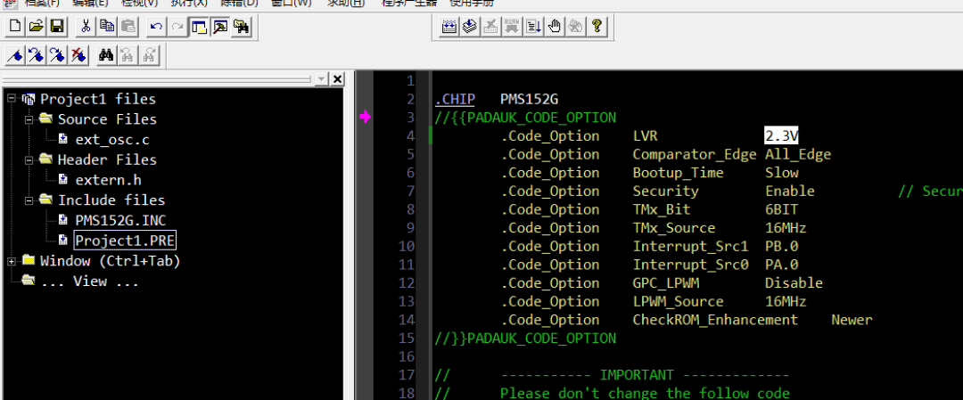
LVR, which stands for Low Voltage Reset, is a circuit protection mechanism that allows a system to automatically reset when the power supply drops below a specific threshold. This helps prevent unpredictable errors or damage to the system under low voltage conditions, ensuring system stability and improving reliability.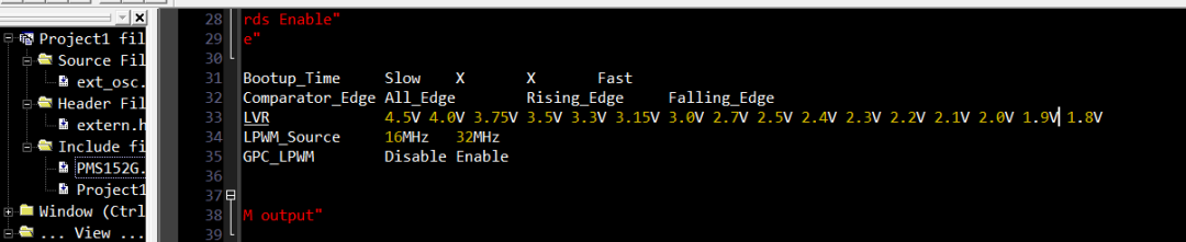 Taking the PMS152G as an example, we can see several values for LVR settings in the .INC file, including 4.5V, 4.0V, 3.75V, 3.3V, 3.0V, 2.7V, 2.5V, 2.4V, 2.3V, etc., with a minimum setting of 1.8V. The PMS152G can operate at a low working voltage, with a minimum of 1.8V, and can execute instructions at a speed of 2 MIPS. So, what is the most reasonable voltage setting for our program? This is related to our instruction execution speed and the required operating voltage of the system. First, the faster the instruction execution speed, the higher the required LVR setting. If set too low, the compiler will prompt an error: “Code option: LVR is too low.” In such cases, the LVR setting needs to be adjusted in the .pre file. As shown in the figure below:
 LVR should not be set too high, nor should it be close to the system’s operating voltage. If it is too close, even slight fluctuations in system voltage may cause a reset. Some engineers have written programs with high programming failure rates, and during program downloads, it can be seen that they mistakenly set the voltage for adjusting the internal high-speed RC clock to 3.3V and also set the LVR to 3.3V. Setting the VDD voltage to the same value as the LVR voltage is a critical error.In systems that require sleep handling, the LVR setting becomes even more important. This is because some IC models from 应广 have a current flowing through them that is significantly higher when operating below the reset voltage. In the design of some battery products, the intention is to stop the system at a certain voltage to minimize power consumption and protect the battery from over-discharge damage. For example, if the LVR is set to 2.7V for the PMS152G, the program can detect low voltage, and at 2.95V, it enters a protection state, at which point the system stops working. This keeps the system in a low power state. However, it is essential to ensure that the current between the protection state and 2.7V remains normal. When the battery voltage drops below 2.7V, the system’s power consumption may actually increase to 60-70uA, which accelerates battery depletion and can lead to over-discharge. Therefore, to better protect the battery, the LVR can be set lower. If allowed by the IDE, directly setting it to 1.8V or 1.9V would be better. This way, after the software system enters the protection state, there is a significant voltage drop space without causing excessive current. Of course, as the voltage decreases, the abnormal current will also become smaller. However, compared to the actual sleep current, the abnormal current will still be relatively large. Some battery-powered devices, when not used for an extended period and then charged, may find that they can no longer be charged. One reason for this could be that the battery was damaged due to over-discharge.Regarding LVR settings, do any of you engineer friends have other suggestions? Feel free to share in the comments.If you are still using QQ and want to get more timely FAE support, feel free to join our QQ group:
 If you want to chat casually, you are also welcome to join the chat group: