AbstractThis study proposes a method for developing cyber-physical systems that starts from a high-level representation of the control algorithm, performs formal analysis of the algorithm, and conducts joint simulation of the algorithm with the controlled system at both high-level (abstracting the target processor) and low-level (including simulation of the target processor). The expected advantages are a smoother and more controllable development process, as well as higher design reliability and accuracy compared to basic model-driven development. As a case study, automatic transmission control has been used to demonstrate the applicability of the proposed method.1 IntroductionSimulation is a fundamental activity in model-driven development (MDD) as it allows developers to implement virtual prototypes of their designs at all required levels of abstraction until the design is refined and verified to the point where it can be prototyped in hardware and code.The existence of design models at different levels of abstraction makes it convenient to use different tools and forms for each model. For example, consider the control part of a cyber-physical system (CPS). This component must implement a high-level control algorithm that can be mathematically defined and modeled and simulated using well-known tools, while also implementing a model of the controlled plant, which is typically built using the same tools, such as Simulink. From now on, the default simulation includes a plant model built with Simulink. Further refinements lead to lower-level designs, including programming code and the hardware platform of the target processor, including system software/microcode. In this paper, the term hardware or platform refers to the physical and software infrastructure that executes the control algorithm. At this level of abstraction, the developed programming code can run on either simulated or real processor architectures. At this point, the hardware platform is a critical issue as it significantly affects system performance and reliability. Accurate simulation of the platform makes it possible to evaluate hardware from different vendors, compare different architectural solutions, and choose the best parameter configurations.However, the formalism and tools required for processor simulation are fundamentally different from those used for high-level design. This mismatch is both conceptual and organizational, as the two levels require different expertise and are potential sources of project delays, design errors, and other issues.This paper introduces the concept of cross-level simulation, which is an MDD approach aimed at bridging the gap between high-level and low-level models, maintaining consistency between them, and further achieving formal verification of the control algorithm. A key point of this concept is that the implementation of the control algorithm is the same for both levels of simulation, and the implementation is automatically generated from a formally verifiable model.Depending on the application characteristics or project constraints, verification can be performed either on the formal model in advance or concurrently with simulation, with both activities cross-checking each other.This approach is summarized in Figure 1, which extends the common development process based on Simulink-like tools and relies on various tools for model building, transformation, and simulation. More specifically:(i) A prototyping environment is used to create high-level, automaton-based models and generate logic-based specifications and C code;(ii) Specifications are verified using a theorem proving environment to validate the control algorithm;(iii) High-level simulation executes the controller code together with the plant model, for example, in Simulink;(iv) Low-level simulation executes the same code on simulated hardware built in the SESAM/VPSim environment to consider timing behavior.In summary, this work extends the common MDD process by:(i) Starting from an abstract formal model;(ii) Automatically generating executable models and verifiable models;(iii) Using formal verification in parallel with simulation;(iv) Relying on joint simulation to achieve modularity and flexibility of the system model;(v) Using the same control code in both high-level and low-level simulations.The expected advantages are (i) a smoother and more controllable process; (ii) higher design reliability and accuracy compared to basic MDD, relying on tools that strengthen model consistency at different levels of abstraction. Specifically, using the same code in high-level and low-level joint simulations.The remainder of this paper is structured as follows: Section 2 presents related work, Section 3 describes the methods and tools for virtual prototyping/verification, Section 4 explains the proposed method, Section 5 demonstrates its application in a case study, and Section 6 summarizes the paper.2 Related WorkModel-driven development primarily relies on simulation to analyze system behavior [25]. In cyber-physical systems, simulation often takes the form of co-simulation [11], which integrates the simulation of heterogeneous subsystems and uses appropriate tools for modeling and simulation.
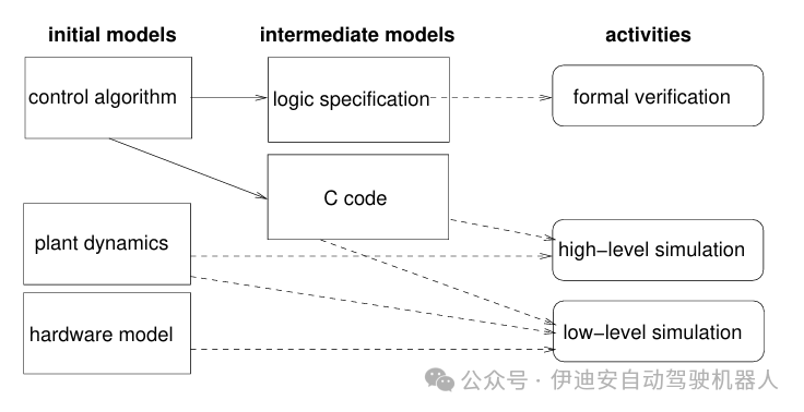 Figure 1: Overview of cross modeling.
Due to the complexity of such systems, formal verification helps assess compliance with safety requirements. Hybrid model checking relies on the formalism of hybrid automata [12] to analyze cyber-physical systems using model checking methods.An example of a model checking tool is HYCOMP [7], which also relies on Satisfiability Modulo Theories [8]. A complementary approach to model checking is theorem proving. Dynamic logic [5] is used with the KeyMaeraX [22] theorem prover, which has been integrated with the SPIRAL environment [23], as described by Franchetti et al. [10]. The framework for integrated simulation and theorem proving is PVSio-web [18], which uses higher-order logic as a modeling language, as described in [9, 20, 3]. None of these works integrate processor simulation into co-simulation.In the field of electronic system design, virtual prototyping is widely used to simulate the behavior of systems to be built. This can better assess hardware/software co-design and provide rapid software development, shortening time to market. Many tools from academic work [14, 6] or electronic design automation vendors [26] meet this need. The cited tools are all based on the IEEE SystemC standard [13] for model sharing. This standard defines a C++ library that provides a complete discrete event simulation environment and design-specific architectural constructs for hardware design at this level of abstraction. The TLM 2.0 standard [1] further extends SystemC, abstracting complex communication channels and protocols into simple function calls for faster simulation.3 BackgroundThis section details the methods and tools used in this work.3.1 PVS, Emucharts, and PVSio-webTheorem proving involves describing a system in some logical language as a theory, expressing its requirements as theorems, and verifying them using automated or interactive theorem proving software. The Prototype Verification System (PVS) [19] is an interactive theorem proving environment based on higher-order specification language, where its variables can cover functions and predicates. Theorems are proven by executing proof steps via commands.Users can create any theory by editing text files, but the PVSio-web toolkit [18] can generate PVS theories from automata created using the Emucharts [16] editor. Emucharts graphs consist of patterns linked by transitions. The graph is complemented by a set of variables whose values define the current state along with the current pattern. Transitions are defined by triggers (events), guards (enabling conditions for variables), and actions (updates of variables). Variables may be distributed over discrete or continuous domains, representing time, state variables, values of time derivatives, and updates in differential equations, thus Emucharts is a type of hybrid automaton defined in [12]. Figure 5 in Section 5.1 shows an example.The PVSio-web toolkit can convert Emucharts into various specifications and programming languages, including Misra C, a reliability-focused version of C [17]. A system model based on high-level automata can then be created, from which PVS theories can be generated to assert its properties, along with executable code automatically generated from the same model.3.2 INTO-CPSCo-simulation [11] is a technique that couples different simulation units together. Complex systems can then be decomposed into many simpler sub-models, and each sub-model can be simulated using its specific language and tools. The Functional Mockup Interface (FMI) [4] is an emerging co-simulation standard where different simulation units (called Functional Mockup Units (FMUs)) are coordinated by a master algorithm responsible for synchronizing and exchanging data between FMUs. The master algorithm adopted in this work is the co-simulation orchestration engine (COE) developed by the INTO-CPS association [15]. The COE requires input on logical connections between FMUs, parameter values, and constraints on the co-simulation time step. The INTO-CPS application also collects and graphically displays data generated from co-simulation experiments.3.3 SESAM/VPSim EnvironmentIn the SESAM [27] CPS design framework, the VPSim [6] tool is designed for rapid assembly and simulation of SoC architectures for design space exploration as well as hardware/software co-design and verification. VPSim uses Python scripts to define architectures composed of SystemC modules, which come from a wide library of commercial simulation components, including CPUs, interconnects, peripherals, and external controllers from different vendors (Xilinx, Renesas, Cadence, etc.). VPSim relies on the QEMU [2] processor simulator to provide rich and fast CPU library models. Since it aims for fast simulation, VPSim is based on a loosely timed model compliant with TLM 2.0.Like all SESAM tools, VPSim supports FMI co-simulation for interoperability of tools throughout the design phase. It is a fully automated solution for exporting hardware/software virtual prototypes as FMUs. This makes co-simulation of the entire CPS possible, as described in [24]. Thus, it can easily interact with other FMI-compliant simulators. The FMU packaging of the VPSim virtual platform can be automatically generated based on a high-level description of the hardware/software platform.4 Cross-Level Modeling, Co-Simulation, and VerificationThe cross-level simulation introduced in Section 1 is discussed below.
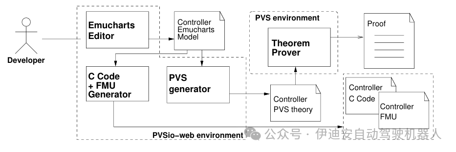 Figure 2: Model generation and formal verification.
4.1 Development ProcessThe initial steps of the development process are illustrated in Figure 2: first, developers use the PVSio-web environment to generate Emucharts models of the analyzed algorithm, then developers use PVS and C code generators to produce PVS theories and Misra C code.In the verification activity, the theories are used for two forms of verification: first, the PVS type checker [21] evaluates the well-formedness of the system model, and then the theorem prover checks its compliance with requirements. The type checker can generate type checking conditions (TCCs), which are statements that must be proven to ensure type correctness. Many TCCs are automatically executed, while others can be proven by the user using one or several commands, but unprovable TCCs reveal incompleteness or inconsistency in the theory. Requirement specifications involve converting desired properties from natural or mathematical language into PVS theorems.
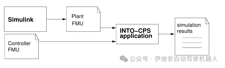 Figure 3: High-level co-simulation.
In the high-level simulation phase, the controller is co-simulated with the plant model to validate it (Figure 3). The latter is built using tools like Simulink and encapsulated in an FMU.In the low-level simulation phase, the controller is compiled and executed on a simulation platform that includes accurate models of real hardware (such as processors, memory, and controllers). At this stage, performance-related properties such as execution time, latency, or cache misses will be evaluated, and alternative hardware components may be assessed (Figure 4).
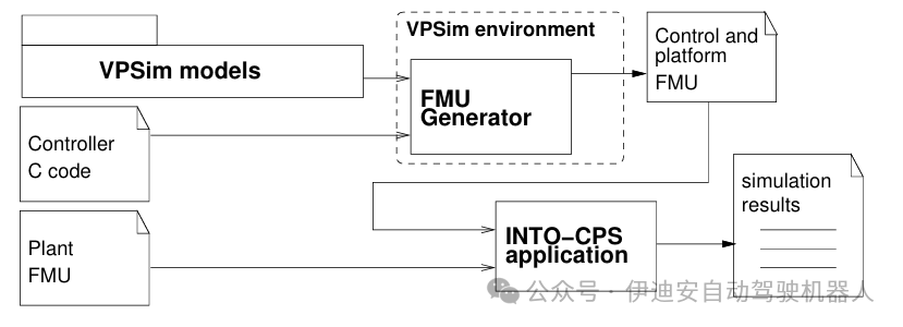 Figure 4: Low-level co-simulation.
Verification or simulation activities (or both) may fail, for example, because the results of the co-simulation are not as expected, or because some TCCs fail to discharge; in this case, the results of the failed activities should be used to refine the Emucharts model, then generate new Misra C code and new PVS theories, and iterate these two activities until both succeed.When type checking and co-simulation succeed, the safety properties of the analyzed sub-model can be specified and proven.4.2 Using VPSim to Simulate ProcessorsVPSim can simulate any architecture using CPU models provided by QEMU, an open-source hardware simulation solution, although it also allows integration with model providers that have SystemC/TLM interfaces, such as ARM Fast Models. By using QEMU for CPU modeling, we can achieve very high simulation speeds. Such high performance is primarily achieved by abstracting architectural aspects of the CPU while maintaining functional accuracy during execution. To provide users with necessary performance statistics, VPSim enriches QEMU models to simulate architectural aspects in the SystemC simulation domain. For this purpose, all models supported by QEMU (including VirtIO) are encapsulated in SystemC modules and executed in the context of SystemC threads. Thus, QEMU models are controlled by the SystemC kernel like any native module and are transparently exposed to users like any other VPSim component. For CPS verification, the VPSim virtual platform can be packaged as an FMU by adding definitions of the necessary FMI interfaces used in the Python front-end interface. VPSim supports models such as CAN controllers in its hardware library.5 Case Study of Automatic Transmission ControlThe case study of this research is based on the automatic transmission controller example from Matlab documentation 1. This example is a Simulink/Stateflow model consisting of five high-level modules:engine, shift logic, transmission, vehicle, and ManeuvresGUI, which drives the simulation by generating throttle and brake signals for overtaking maneuvers.The shift logic block is a hybrid automaton defined in Stateflow that issues upshift and downshift commands to the transmission based on a shift schedule considering the current gear, vehicle speed, and throttle position.If the vehicle is traveling at an intermediate speed between the upshift and downshift thresholds for the current gear and throttle, the shift logic controller is in a stable state. If the throttle or speed exceeds the threshold, the controller moves to one of the two waiting states (upshift or downshift). If the speed remains beyond the threshold for a given time, the corresponding shift command is issued, and the controller moves to the stable state of the new gear.5.1 High-Level Virtual PrototypeThe ShiftLogic block has been redesigned and packaged into an FMU as described in Section 4.1. Another FMU generated by Simulink contains the other four blocks. These two FMUs are then co-simulated in INTO-CPS.5.1.1 Emucharts Model of ATCThe behavior of the ATC is specified by the shift schedule. Using the data from the above example, the shift schedule is defined by the functions represented in Tables 1 and 2.Each row marked as n m shows the threshold speed values (in miles per hour) for shifting from gear to gear lever, with continuous intervals of throttle position t% (in percentage).Table 1: Shift schedule, upshift speed threshold.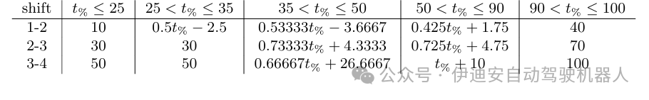 Table 2: Shift schedule, downshift speed threshold.
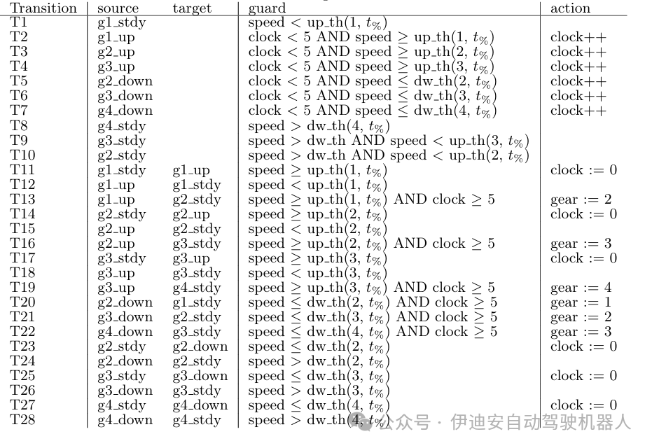
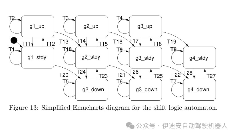
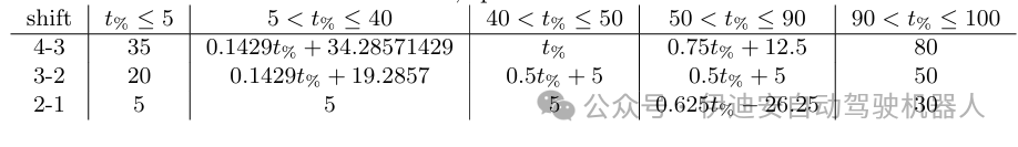 The shift schedule has been modeled as an Emucharts graph. Figure 5 shows a fragment of the graph relative to the two lower gears, while the complete graph drawn in a more compact form (Figure 13) is in the appendix, including the transition definitions. Each transition is labeled, followed by guards in brackets, possibly with actions in parentheses.In the graph, the stdy mode represents the stable conditions of the ATC, while the up and down modes represent the waiting phases before the ATC issues upshift or downshift commands when the speed exceeds the respective thresholds for a sufficient time.The transitions depend on the variables:discrete variables clock and gear, and continuous variables tht (throttle), up th (upshift threshold), dw th (downshift threshold), and speed.The variable clock is a timer that can increment by one or reset, and gear is the controller output.The flow conditions for input variables tht and speed [12] are defined externally by the Vehicle and ManeuvresGUI models, while the flow conditions for up th and dw th are given by the shift schedule in Tables 1 and 2, respectively.
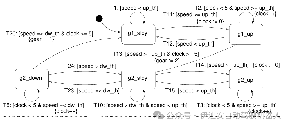 Figure 5: Emucharts fragment of the shift logic automaton.
5.1.2 Releasing TCC for ATCThe Emucharts model of ATC originates from the state flow machine in the cited Matlab example. Type checking of the PVS theory generated from the first version of the Emucharts produced unprovable TCCs. One is a coverage TCC, indicating that all guards for transitions are the same, meaning at least one transition is enabled. The complementary mutual exclusion TCC requires that at most one transition is enabled. The issue is that some transitions are implicit in the state flow model, and this is resolved by explicitly adding the required transitions to the Emucharts model. These transitions are marked in bold in Figure 13 as T1, T8, T9, and T10. This is an example of how complex type systems and automatic checking can help uncover hidden assumptions that are often sources of errors.5.1.3 Co-Simulation of ATCFigure 6 shows the architecture of the high-level co-simulation. The co-simulation is executed with a fixed time step of 0.1 seconds, lasting for 80 seconds of simulation time. Figure 7 shows the results of the co-simulation run. These results are consistent with those obtained using the original Simulink model, as the shapes of the throttle and speed curves between the first and third upshifts match the plots in the MATLAB documentation, except for the initial speed values and initial transients, as discussed in Section 5.2.
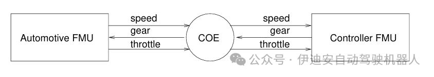 Figure 6: High-level co-simulation architecture
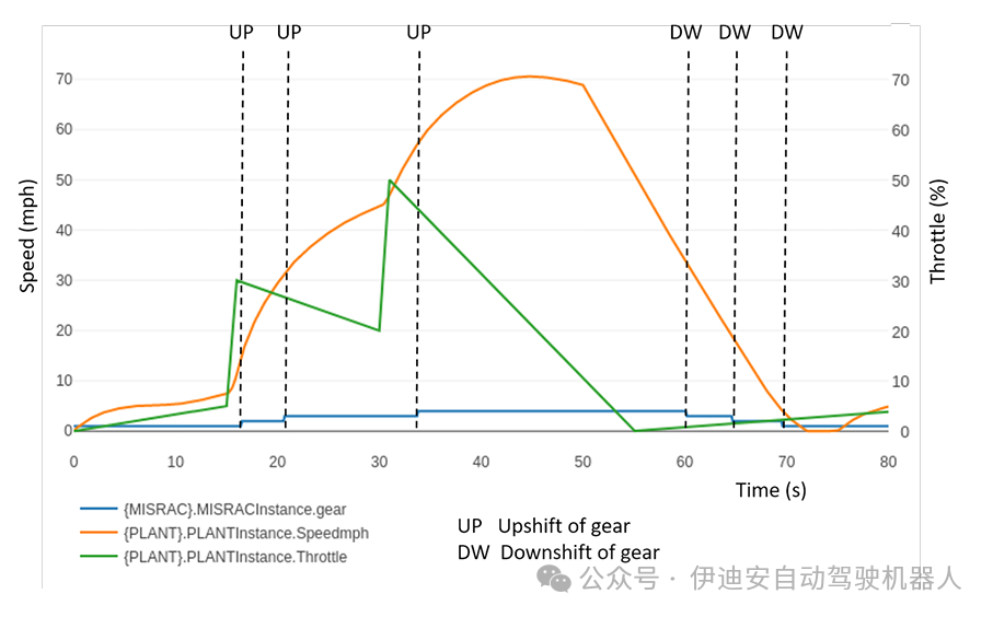 Figure 7: High-level control co-simulation.
5.1.4 Verification Process of ATCFor example, one of the safety properties of the ATC algorithm is that it can never move from a state where gear equals g to a state where gear equals g2 in one step. This natural language statement can be translated into a main theorem in PVS, where abs is the absolute value function:
gear_T: TYPE = {x: posnat | x<=4}main_th: THEOREMFORALL(N:nat, g:gear_T):kth_step(N)gear = g => abs(kth_step(N+1)gear- g) < 2where kth_step(N) is a data structure containing the values of all variables at step N, and gear selects the value of gear. The proof is completed by induction on the number of steps and analyzing the different values of gear separately. The proof relies on several lemmas. For example, it must be proven that for any gear, the computed upshift threshold speed (compute UP TH(s)up th) is greater than the downshift threshold speed (compute UP TH(s)dw th):UPgtDW: LEMMAFORALL (s:State):compute_UP_TH(s)up_th > compute_DW_TH(s)dw_thAnother lemma excludes direct transitions between two stable states:gear1:LEMMA FORALL(N:nat):kth_step(N)mode=g1_steady => kth_step(N+1)mode /= g2_steadyVerifying this theorem and similar theorems ensures the functional correctness of the control algorithm.5.2 Co-Simulation with VPSimFigure 8 shows the architecture for low-level simulation using VPSim. This architecture is very similar to the high-level scenario, with the only difference being that the controller FMU has been replaced by the FMU generated by VPSim. The FMU generated by VPSim simulates an ARMv8 64-bit architecture cluster. This cluster contains a single-core processor with private L1 and L2 caches, connected to on-chip interconnects and peripherals. More cores and clusters can be added in the future for more complex applications. The architecture executes a Linux operating system that supports the ShiftLogic application.
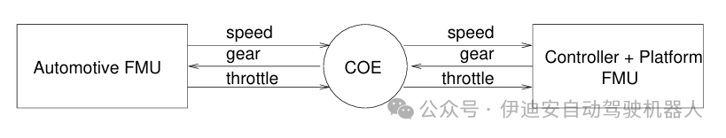 Figure 8: Low-level co-simulation architecture.
Thus, the VPSim FMU requires initial time to boot the operating system before executing the ShiftLogic algorithm, while the MisraC FMU executes the algorithm from the start of the co-simulation. To compare the two architectures, during the first few seconds of co-simulation, the throttle value remains close to zero.VPSim can capture the timing behavior of the system. Therefore, the duration of the application code directly affects the evolution of the FMU output and may change the FMU output.Simulations have been executed with different execution times of the ATC, obtained by adding delay loops in the original code. When the execution speed of the ATC is faster than the FMI host’s required FMI simulation step (Figure 9), its behavior is similar to that achieved using high-level simulation implementation. (The functions fmi2set and fmi2get are write and read operations, while the function fmi2DoStep triggers the execution of a simulation step.) In this case, Figure 11 shows the behavior of the co-simulation with the VPSim FMU: the resulting behavior is consistent with that obtained previously using high-level co-simulation. Conversely (Figure 10), when the execution speed of the ATC is slower than the interval of calling fmi2DoStep, the output value changes differently from future simulation steps.Combining the two simulation levels can better emphasize the insufficient execution speed of the examined code. In fact, when the application execution speed is appropriate, the behavior is consistent across all verification levels, as expected. However, it is worth noting that even if the co-simulation step can be set to arbitrarily small values, this will introduce new differences, as low-level simulation has processing delays compared to high-level simulation. If achievable, it is recommended that users keep the duration of the simulation step consistent with the expected control decision deadlines.To further improve model alignment not affected by this limitation, it may also be beneficial in future work to model the target execution time during high-level simulation by appropriately delaying control decisions. This would make the behavior of the high-level model independent of the choice of simulation step. Similarly, even if the control code executes too quickly, low-level simulation results should not be provided prematurely. This may be considered in real-time code, as control decisions in real-time code are never output before the target deadline.
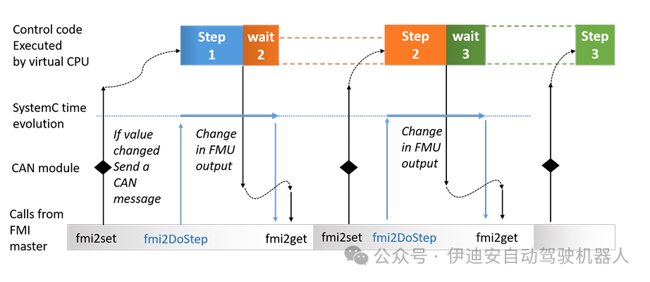 Figure 9: Co-simulation of VPSim generated FMU with fast ATC execution.
5.3 Results and DiscussionFigure 11 can be compared with Figure 7: except for the first few seconds, where the processor is still booting and gear equals zero, the behavior of the gear variable is the same in both cases. This result implies that the time required to execute the ATC on the simulated processor is less than the step length chosen for co-simulation (0.1 seconds).To highlight the advantages of low-level co-simulation, the ATC algorithm has been artificially extended, with redundant code increasing its computation time, thus making the execution time of the ATC greater than the co-simulation step length.Figure 12 shows a comparison between the low-level and high-level behaviors of the gear variable when using the extended code.A slight time delay in the variable behavior can be noted, which is due to different time management: high-level co-simulation always executes the entire ATC algorithm within the co-simulation step, while low-level co-simulation now requires more co-simulation steps.Note that the delay in the first two gear transitions of low-level co-simulation affects the speed value, causing it to increase, so that the next gear transition occurs earlier relative to high-level simulation, and obviously without delay.
 Figure 10: Co-simulation of VPSim generated FMU with slow ATC execution.
The co-simulation results indicate that the underlying hardware performance (e.g., computation speed) must be considered to ensure that the device can be controlled within the step length range. High-level simulation hides system performance issues that virtual prototypes can highlight.In all co-simulation runs, whether high-level or low-level, the results obtained using PVS hold, as two gear transitions are never executed in two adjacent steps, thus validating the results obtained in Section 5.1.4. Of course, time-related properties will be affected by different time management, so an additional step will need to be added to the verification process, namely the specification of the processor in PVS, but this will be the subject of future work.
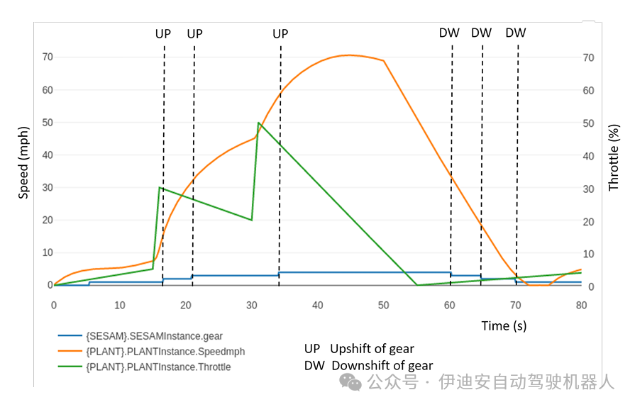 Figure 11: Low-level control co-simulation
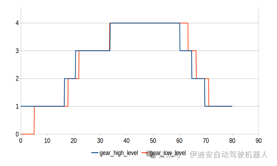 Figure 12: Gear shifting in high and low-level simulations
6 ConclusionThis study presents a method for analyzing control algorithms deployed on automotive systems. The method uses models at different levels of abstraction: a more abstract high-level model consisting of executable code of the control algorithm, and a more accurate low-level model that also includes simulation of the hardware executing the code. High-level analysis provides information about the functional correctness of the model by leveraging formal reasoning tools (e.g., PVS theorem prover) and simulation tools (e.g., INTO-CPS), while low-level analysis provides information about the execution performance of the selected hardware by leveraging VPSim. The proposed method also incorporates the physical components of the vehicle into the analysis using FMI co-simulation.In the development of CPS, especially safety or mission-critical CPS, both levels of analysis are required. It is meaningless to directly perform software/hardware integration before verifying and possibly validating the controller design, as it is pointless to choose a hardware platform without assessing its adequacy in terms of timing constraints and evaluating its performance. This work aims to provide a framework to maintain consistency among the three key aspects of development (i.e., formal verification, high-level, and low-level modeling) as much as possible.The case study of the automatic transmission controller algorithm serves as a proof of concept for the methods and tools involved in safety-critical areas such as automotive applications. The results emphasize that the performance of the selected hardware can be assessed: if the simulated processor is fast enough to adapt the execution of the algorithm within the co-simulation time steps, then the behavior of low-level co-simulation is the same as that of high-level co-simulation; otherwise, co-simulation will show different behaviors. The proposed method is applied to an ARMv8 64-bit single-core processor with private L1 and L2 caches, which is used for many automotive processors (e.g., NXP S32V). In the future, more cores will be added to consider high-end processors (such as Rhea1, expected to be a result of the European Processor Initiative project) and more complex safety-critical applications such as autonomous driving and vehicle dynamics model predictive control.AcknowledgmentsThe authors would like to thank the reviewers for their helpful comments and suggestions.Authors: Cinzia Bernardeschi, Andrea Domenici, Maurizio Palmieri, Sergio Saponara Dept. of Information Engineering, University of Pisa, Italy.Original: arpi.unipi.it/retrieve/e0d6c931-7b3d-fcf8-e053-d805fe0aa794/CoSim-CPS2020.pdfTranslation: Joyce Proofreading: MikeThis article is based on the Creative Commons text sharing protocol: https://creativecommons.org/licenses/by-sa/4.0/References [1] Accelera: TLM-2.0 Language Reference Manual. https://www.accellera.org/images/ downloads/standards/systemc/TLM_2_0_LRM.pdf (2009)[2] Bellard, F.: QEMU, a Fast and Portable Dynamic Translator. In: Proceedings of the Annual Conference on USENIX Annual Technical Conference. p. 41. ATEC 05, USENIX Association, USA (2005)[3] Bernardeschi, C., Domenici, A., Masci, P.: A PVS-Simulink Integrated Environment for Model-Based Analysis of Cyber-Physical Systems. IEEE Transactions on Software Engi neering 44(6), 512533 (2018)[4] Blochwitz, T., Otter, M., Akesson, J., Arnold, M., Clau , C., Elmqvist, H., Friedrich, M., Junghanns, A., Mauss, J., Neumerkel, D., Olsson, H., Viel, A.: Functional Mockup Interface 2.0: The Standard for Tool independent Exchange of Simulation Models. In: Proceedings of the 9th International MODELICA Conference. pp. 173184. No. 76 in Linkoping Electronic Conference Proceedings (2012)[5] Bohrer, B., Rahli, V., Vukotic, I., Volp, M., Platzer, A.: Formally verified differential dynamic logic. In: Proceedings of the 6th ACM SIGPLAN Conference on Certi ed Programs and Proofs. pp. 208221. CPP 2017, ACM (2017). https://doi.org/10.1145/3018610.3018616[6] Charif, A., Busnot, G., Mameesh, R.H., Sassolas, T., Ventroux, N.: Fast virtual prototyping for embedded computing systems design and exploration. In: Chillet, D. (ed.) Proceedings of the Rapid Simulation and Performance Evaluation: Methods and Tools, RAPIDO 2019, Valencia, Spain, January 21-23, 2019. pp. 3:13:8. ACM (2019). https://doi.org/10.1145/3300189.3300192[7] Cimatti, A., Griggio, A., Mover, S., Tonetta, S.: HyComp: An SMT-based model checker for hybrid systems. In: International Conference on Tools and Algorithms for the Construction and Analysis of Systems. pp. 52 67. Springer (2015)[8] De Moura, L., Bj rner, N.: Satis ability modulo theories: introduction and applications. Communications of the ACM 54(9), 6977 (2011)[9] Domenici, A., Fagiolini, A., Palmieri, M.: Integrated simulation and formal veri cation of a simple autonomous vehicle. In: International Conference on Software Engineering and Formal Methods. SEFM 2017. Lecture Notes in Computer Science, vol 10729. pp. 300314. Springer (2017)[10] Franchetti, F., Low, T.M., Mitsch, S., Mendoza, J.P., Gui, L., Phaosawasdi, A., Padua, D., Kar, S., Moura, J.M.F., Franusich, M., Johnson, J., Platzer, A., Veloso, M.M.: High assurance spiral: End-to-end guarantees for robot and car control. IEEE Control Systems 37(2), 82103 (April 2017). https://doi.org/10.1109/MCS.2016.2643244[11] Gomes, C., Thule, C., Broman, D., Larsen, P.G., Vangheluwe, H.: Co-simulation: a survey. ACM Computing Surveys (CSUR) 51(3), 133 (2018)[12] Henzinger, T.A.: The theory of hybrid automata. In: M.K., I., R.P, K. (eds.) Veri cation of Digital and Hybrid Systems, NATO ASI Series (Series F: Computer and Systems Sciences), vol. 170, pp. 265292. Springer, Berlin, Heidelberg (2000). https://doi.org/10.1007/978-3 642-59615-5 13[13] IEEE: IEEE Standard for Standard SystemC Language Reference Manual. IEEE Std 1666 2011 (Revision of IEEE Std 1666-2005) pp. 1638 (2012)[14] Imperas Ltd.: Open Virtual Platforms. http://www.ovpworld.org/ (2020) [15] Larsen, P.G., Fitzgerald, J., Woodcock, J., Fritzson, P., Brauer, J., Kleijn, C., Lecomte, T., Pfeil, M., Green, O., Basagiannis, S., Sadovykh, A.: Integrated tool chain for model-based design of Cyber-Physical Systems: The INTO-CPS project. In: 2016 2nd International Workshop on Modelling, Analysis, and Control of Complex CPS (CPS Data). pp. 16 (April 2016). https://doi.org/10.1109/CPSData.2016.7496424[16] Masci, P., Zhang, Y., Jones, P., Oladimeji, P., DUrso, E., Bernardeschi, C., Curzon, P., Thimbleby, H.: Combining PVSio with State flow. In: Proceedings of the 6th NASA Formal Methods Symposium (NFM2014). pp. 209214. Springer-Verlag (2014)[17] Mauro, G., Thimbleby, H., Domenici, A., Bernardeschi, C.: Extending a user interface prototyping tool with automatic MISRA C code generation. In: Dubois, C., Masci, P., Mery, D. (eds.) Third Workshop on Formal Integrated Development Environments. Elec tronic Proceedings in Theoretical Computer Science, vol. 240, pp. 5366. Open Publishing Association (2017). https://doi.org/10.4204/EPTCS.240.4[18] Oladimeji, P., Masci, P., Curzon, P., Thimbleby, H.: PVSio-web: a tool for rapid prototyp ing device user interfaces in PVS. In: FMIS2013, 5th International Workshop on Formal Methods for Interactive Systems, London, UK, June 24, 2013 (2013)[19] Owre, S., Rushby, J., Shankar, N.: PVS: A prototype veri cation system. In: Kapur, D. (ed.) Automated Deduction CADE-11, Lecture Notes in Computer Science, vol. 607, pp. 748752. Springer Berlin Heidelberg (1992). https://doi.org/10.1007/3-540-55602-8 217 [20] Palmieri, M., Bernardeschi, C., Masci, P.: A framework for FMI-based co-simulation of humanmachine interfaces. Software and Systems Modeling 19(3), 6016023 (2020)[21] Palmieri, M., Macedo, H.D.: Automatic Generation of Functional Mock-up Units from For mal Speci cations. In: 3rd Workshop on Formal Co-Simulation of Cyber-Physical Systems A satellite event of SEFM 2019 (2019), in press[22] Platzer, A., Quesel, J.D.: KeYmaera: A Hybrid Theorem Prover for Hybrid Systems (Sys tem Description). In: Armando, A., Baumgartner, P., Dowek, G. (eds.) Automated Reason ing, Lecture Notes in Computer Science, vol. 5195, pp. 171178. Springer Berlin Heidelberg (2008). https://doi.org/10.1007/978-3-540-71070-7 15[23] Puschel, M., Moura, J.M.F., Johnson, J.R., Padua, D., Veloso, M.M., Singer, B.W., Xiong, J., Franchetti, F., Gacic, A., Voronenko, Y., Chen, K., Johnson, R.W., Rizzolo, N.: SPI RAL: Code Generation for DSP Transforms. Proceedings of the IEEE 93(2), 232275 (Feb 2005). https://doi.org/10.1109/JPROC.2004.840306[24] Saidi, S.E., Charif, A., Sassolas, T., Le Guay, P.G., Souza, H.V., Ventroux, N.: Fast Virtual Prototyping of Cyber-Physical Systems using SystemC and FMI: ADAS Use Case. In: Proceedings of the 30th International Workshop on Rapid System Prototyping (RSP19). pp. 4349 (2019)[25] Selic, B.: The Pragmatics of Model-Driven Development. IEEE Software 20(5), 1925 (2003). https://doi.org/10.1109/MS.2003.1231146[26] Synopsys: Virtualizer. https://www.synopsys.com/verification/ virtual-prototyping/virtualizer.html (2020)[27] Ventroux, N., Guerre, A., Sassolas, T., Moutaoukil, L., Blanc, G., Bechara, C., David, R.: SESAM: An MPSoC Simulation Environment for Dynamic Application Processing. In: 2010 10th IEEE International Conference on Computer and Information Technology. pp. 1880 1886 (2010). https://doi.org/10.1109/CIT.2010.322AppendixTable 3 shows the transition definitions of the simplified Emucharts graph shown in Figure 13. The uphandwth function implements the shift schedule specifications in Tables 1 and 2.Table 3: Shift logic transitions.