Original Author:
STM32 Chinese Community User Sanjie Dog


This is the third review post for the NUCLEO_L552ZE_Q development board. The previous post introduced how to set up the development environment on the Windows platform. Now that the environment is ready, we can start writing programs for testing (I won’t be writing programs myself, as I will never be able to write programs in my lifetime, thanks to STM32CubeMX). Yes, STM32CubeMX has already written the basic program framework, and for basic testing, you only need to type a few letters. It’s truly a must-have for lazy people, haha.
Without further ado, I believe many friends who have worked with microcontrollers know that the first step when getting a new microcontroller is to test the input and output functions of the GPIO ports. The output function is to light up an LED, and the input function is to scan buttons. So, let’s follow this unwritten rule and start with the input and output functions of the GPIO ports.
Review Content
1. Create a new MDK-ARM project using STM32CubeMX to create a new project;
2. Implement the GPIO port level output function to control the red LED on the NUCLEO_L552ZE_Q development board to blink;
3. Implement the GPIO port level input function to use the USER BUTTON on the NUCLEO_L552ZE_Q development board to control the blinking frequency of the red LED.
Creating MDK-ARM Project
Before we start, we need to understand how to use STM32CubeMX to create a new project.
01 Create Directory
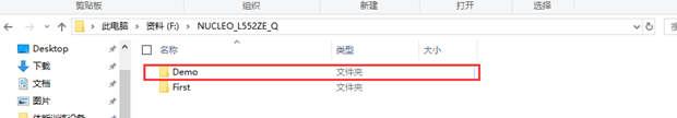
Create a new folder on your computer’s disk. This folder is not the project directory; I will explain which one is the project directory later. Note that the folder name, parent name, and grandparent name, etc., must not contain any Chinese characters! Not even half a Chinese character! You can try it if you don’t believe me. For demonstration, I will create a folder named Demo, as shown in the figure below.
02 Create STM32CubeMX Project
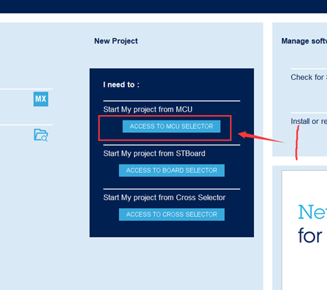
1. Open STM32CubeMX, and left-click on “New Project” and then on “ACCESS TO MCU SELECTOR“;
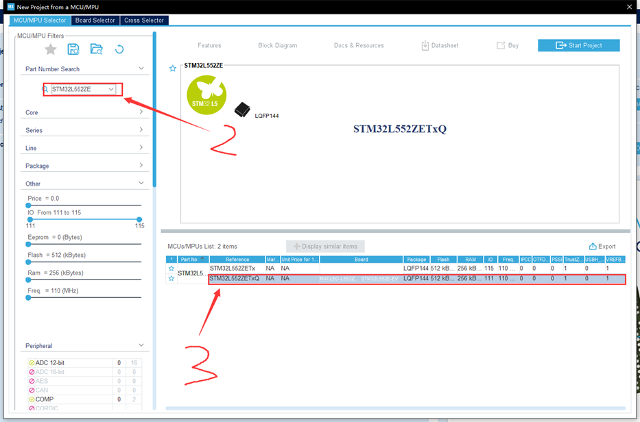
2. In the pop-up window “New Project from a MCU/MPU“, enter the required microcontroller model in the search box on the left. Here, I will enter “STM32L552ZE“;
3. Then select the required microcontroller model from the “MCUs/MPUs List” in the lower left corner. Here, I will choose STM32L552ZET6Q, and double-click on the microcontroller model;
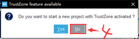
4. A pop-up window will ask if you want to use TrustZone. I choose No, and then an STM32CubeMX project is created.
03 Configure STM32CubeMX Project
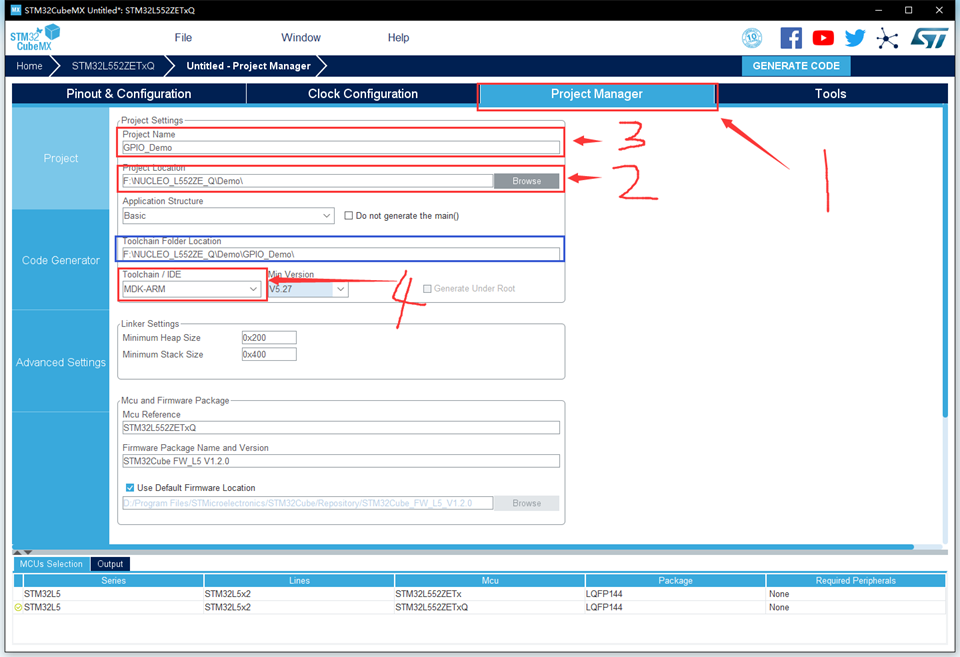
1. Set project properties by clicking on the “Project Manager” option at the top of the STM32CubeMX project window, and switch to “Project” on the far left;
2. In “Project Location”, select the folder created in the first step;
3. In “Project Name”, enter the project name (it cannot be in Chinese). The entered project name will be the root directory of this project, as shown in the blue box;
4. In “Toolchain / IDE”, select “MDK-ARM”, and keep the others as default, as shown in the figure below;
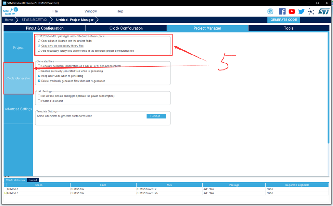
5. Switch to “Code Generator” on the far left. In the right section “STM32Cube MCU packages and embedded software packs”, there are three options, which mean to copy all library files to the project directory, only copy the required library files to the project directory, or only reference the required library files in the project file (the library files are located in the STM32CubeMX installation directory). I choose the second option;
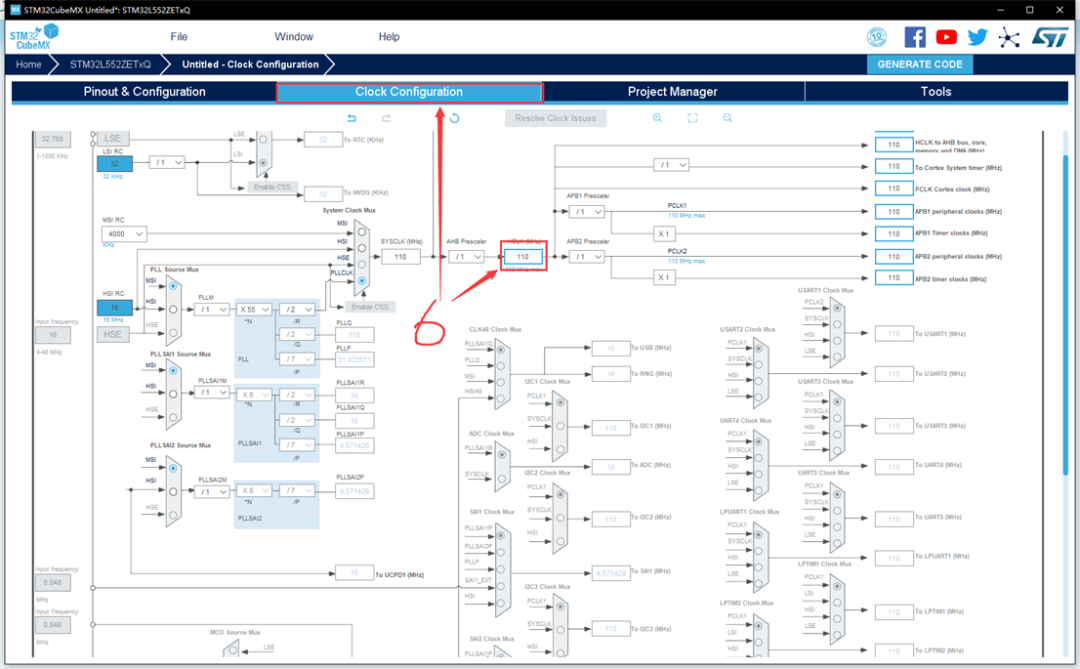
6. Set clock properties by clicking on the “Project Manager” option at the top of the STM32CubeMX project window. In “HCLK(MHz)”, enter the required clock frequency and press Enter. In the pop-up prompt, select Ok. I entered the maximum clock frequency of STM32L552ZET6Q: 110MHz, and kept the others as default: internal high-speed clock 16MHz and internal low-speed clock 32KHz;
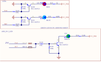
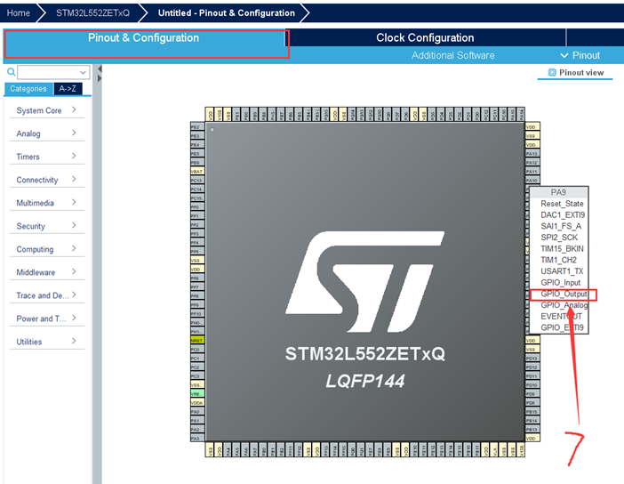
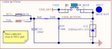
7. Configure the GPIO to light up the LED. The NUCLEO_L552ZE_Q development board has three LEDs: red, green, and blue. According to the information provided in the schematic, the red, green, and blue LEDs are connected to the microcontroller pins PA9, PC7, and PB7, respectively. I chose the classic red LED. In “Pinout & Configuration”, left-click on the PA9 pin on the microcontroller model (the 8th pin from the top on the right side), and select “GPIO_Output”. Thus, the STM32CubeMX project is configured.
04 Save STM32CubeMX Project
Click on “File“, and select “Save Project“.
05 Generate MDK-ARM Project
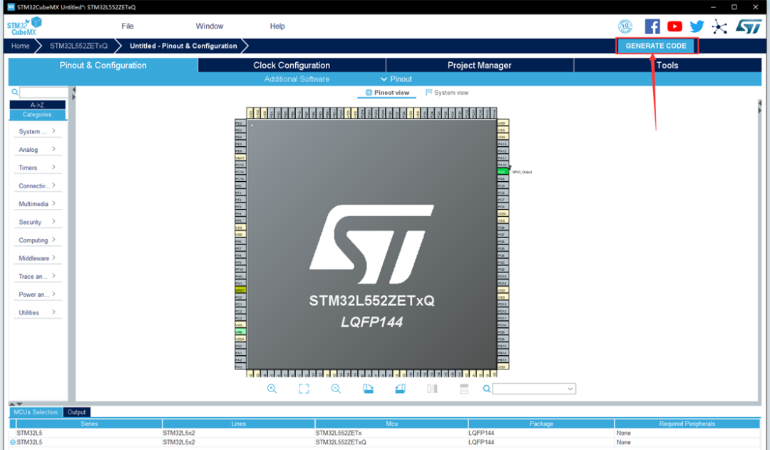
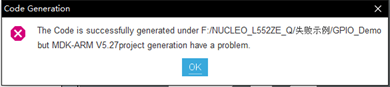
Left-click on the “GENERATE CODE” button in the upper right corner, and the software will automatically generate a code project based on the previous configuration. If there are Chinese characters in the directory created in the first step, an error message will appear during this step, causing the project creation to fail. Therefore, special attention is needed.
GPIO Port Level Output Function: Light Up an LED 01 Understand the Project Directory Structure
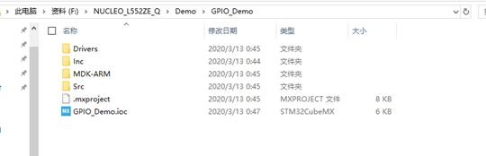
irvers: Stores the STM32 firmware library and the CMSIS library provided by ARM. Usually, there is no need to modify the contents of the files inside;
inc: Stores the user-written .h files, and the contents of the files can be modified;
MDK-ARM: Stores the MDK project files and the STM32 startup files. The contents of the files usually do not need to be modified;
src: Stores the user-written .c files, and the contents of the files can be modified.
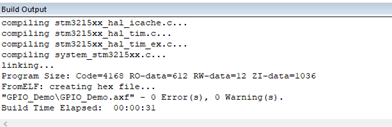
02 In the MDK-ARM folder, double-click the .uvprojx project file. There is no need to make changes; just link it once to check for issues. The result should be 0 errors, 0 warnings.
03
Open the main.c file, find the main() function, and add the following code inside the main function’s while loop, which means to toggle the PA9 pin every 500ms to make the red LED blink.

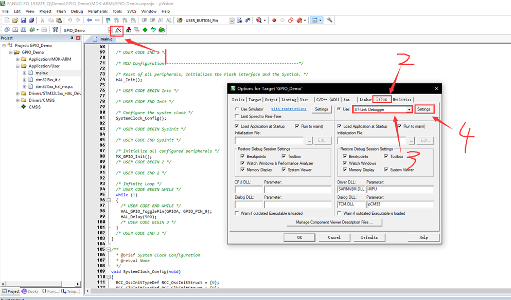
04 Configure Target Attributes
1. Click on the magic wand at the top of the motor window to pop up the configuration window;
2. Switch to the “Debug” option;
3. Select the debugger; I use the ST-Link Debugger;
4. On the left side of the motor, click on “Settings”;
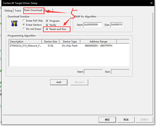
5. In the pop-up window, switch to the “Flash Download” option, check “Reset and Run” so that the program will automatically reset and run after being burned into the microcontroller.
6. Click “OK” to confirm the modifications, then compile and link the project again, resulting in 0 errors, 0 warnings.
05 Burn the Program
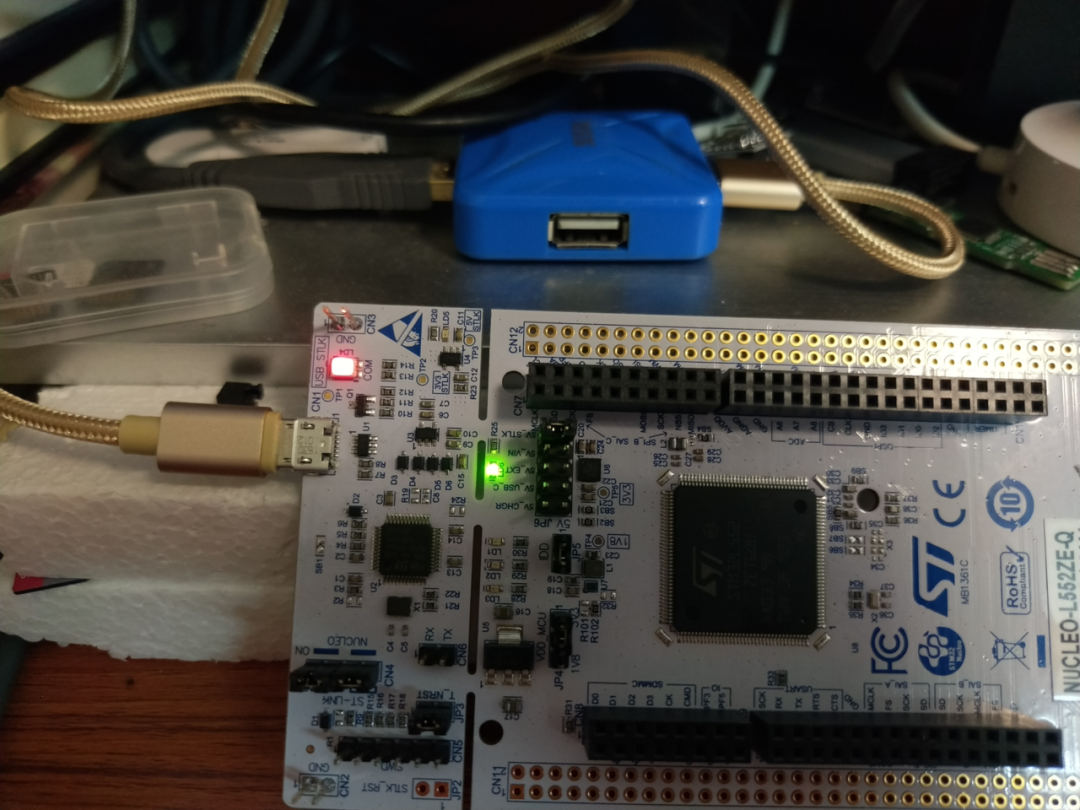
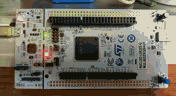
1. Use a Micro USB data cable to connect the computer to the ST-Link USB-A port on the development board. If you haven’t installed the driver, you can check my previous post, which has attachments at the end. If the LD4 on the development board lights up red and LD6 lights up green, it indicates a normal connection.
2. Click the download button in the upper left corner of the MDK software to start downloading the program to the microcontroller for execution.
3. Observe the operation; the red LED starts blinking, indicating that the GPIO port can output high and low levels normally.
GPIO Port Level Input Function: Button Scanning 01 Regenerate MDK-ARM Project
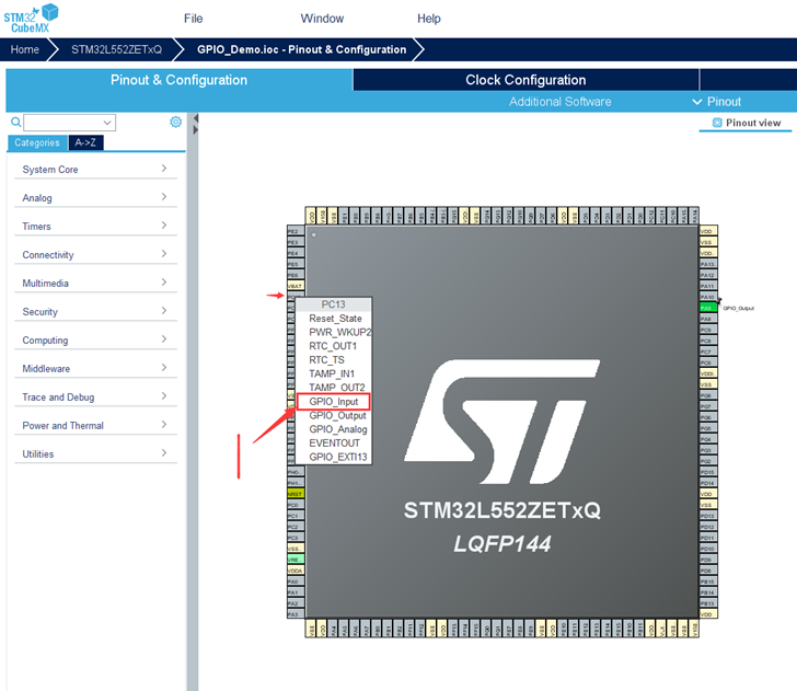
Close the MDK-ARM project. According to the schematic, the USER button on the development board is connected to the PC13 pin of the microcontroller. Return to the STM32CubeMX project, and left-click on the PC13 pin on the microcontroller model (the 7th pin from the top on the left side of the chip model), and select “GPIO_Input”. Save the STM32CubeMX project and click “GENERATE CODE” to regenerate the code.
02 Implement Button Scanning Code
1. Open the MDK-ARM project, and at the beginning of the main function in the main.c source file, add the following code to declare two local variables.

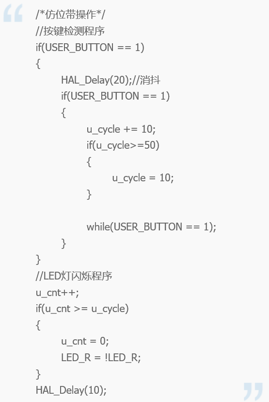
2. Inside the while loop of the main function, add the following code to implement button scanning and LED blinking functionality.

3. After modifying, compile and link the code, burn the code to the development board, and press the USER button on the lower left of the development board to observe the changes in the blinking frequency of the red LED. The actual situation is as follows:
Bit-Banding Operation: Achieving IO Port Operation Method Similar to 51 Microcontroller
Friends who have used the ZhiDian Atom Cortex_M3 or Cortex_M4 series microcontroller development boards should have encountered the bit-banding operation function. In the authoritative guide for Cortex_M3, section 5.5 has the following introduction.
In CM3, there are two areas that implement bit-banding. One is the lowest 1MB range of the SRAM area, and the second is the lowest 1MB range of the on-chip peripheral area. These two bit-banding addresses can be used like ordinary RAM, and they also have their own “bit-banding alias area”. The bit-banding alias area expands each bit into a 32-bit word. When you access these words through the bit-banding alias area, you can achieve access to the original bits.
The bit-banding area and the bit-banding alias area mentioned in the text have the following correspondence.
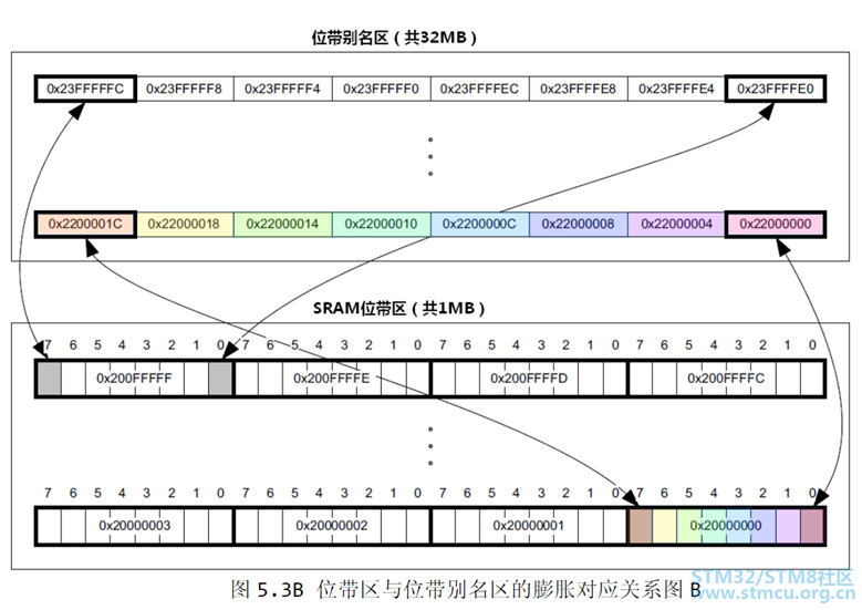
The GPIO port addresses of the STM32 microcontroller are within the lowest 1MB range of the on-chip peripheral area, meaning that you can manipulate a corresponding bit in the peripheral register of the on-chip peripheral area through each address in the bit-banding alias area. Writing 1 to an address in the bit-banding alias area will set the corresponding bit in the peripheral register of the on-chip peripheral area to 1. Reading the value of an address in the bit-banding alias area will return the value of the corresponding bit in the peripheral register of the on-chip peripheral area. The level of each pin of the GPIO port is controlled by each bit in the ODR register and can be obtained through a bit in the IDR register. However, I have checked the manual for Cortex_M33 and did not find this bit-banding alias area, meaning that Cortex_M33 does not have bit-banding operation functionality. However, I can implement similar operations by defining a bit-field structure. The implementation code is as follows:
typedef struct
{
uint16_t OD0 : 1;
uint16_t OD1 : 1;
uint16_t OD2 : 1;
uint16_t OD3 : 1;
uint16_t OD4 : 1;
uint16_t OD5 : 1;
uint16_t OD6 : 1;
uint16_t OD7 : 1;
uint16_t OD8 : 1;
uint16_t OD9 : 1;
uint16_t OD10 : 1;
uint16_t OD11 : 1;
uint16_t OD12 : 1;
uint16_t OD13 : 1;
uint16_t OD14 : 1;
uint16_t OD15 : 1;
} ODR_TypeDef;
#define PAin(n) ( ( GPIOA->IDR&(1 << (n)) )>>n )
#define PBin(n) ( ( GPIOB->IDR&(1 << (n)) )>>n )
#define PCin(n) ( ( GPIOC->IDR&(1 << (n)) )>>n )
#define PDin(n) ( ( GPIOD->IDR&(1 << (n)) )>>n )
#define PEin(n) ( ( GPIOE->IDR&(1 << (n)) )>>n )
#define PFin(n) ( ( GPIOF->IDR&(1 << (n)) )>>n )
#define PGin(n) ( ( GPIOG->IDR&(1 << (n)) )>>n )
#define PAout(n) ( ((ODR_TypeDef *)(&(GPIOA->ODR)))->OD##n )
#define PBout(n) ( ((ODR_TypeDef *)(&(GPIOB->ODR)))->OD##n )
#define PCout(n) ( ((ODR_TypeDef *)(&(GPIOC->ODR)))->OD##n )
#define PDout(n) ( ((ODR_TypeDef *)(&(GPIOD->ODR)))->OD##n )
#define PEout(n) ( ((ODR_TypeDef *)(&(GPIOE->ODR)))->OD##n )
#define PFout(n) ( ((ODR_TypeDef *)(&(GPIOF->ODR)))->OD##n )
#define PGout(n) ( ((ODR_TypeDef *)(&(GPIOG->ODR)))->OD##n )
This code can be encapsulated in a header file for calling, and the usage method is the same as that of the ZhiDian Atom source code.

Conclusion
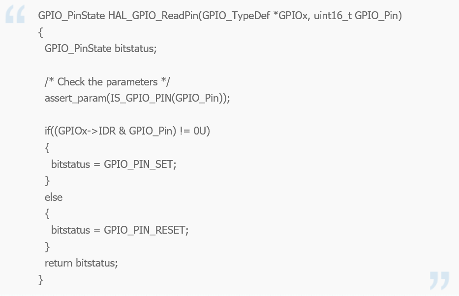
As can be seen, with the help of STM32CubeMX, implementing some basic functional code is quite convenient. Additionally, with the support of the HAL firmware library, regardless of how the underlying registers of the microcontroller change, the HAL firmware library has already unified and encapsulated them into consistent function names, making it very convenient to use. The GPIO port operations tested this time mainly used two functions: HAL_GPIO_TogglePin and HAL_GPIO_ReadPin, both of which are quite simple to implement, directly manipulating registers:

This time we introduced the use of GPIO ports. Since the length of the article is already too long, it took a whole day to finish writing. I will introduce some other basic functions next time when I have time.