In the upgrade and transformation of old equipment projects, it is inevitable to involve the replacement and upgrade of PLCs. However, sometimes the original PLC program of the control system is lost, and a complete annotated original program cannot be found; at other times, the original program may contain proprietary technology blocks; or sometimes the GSD file for the original PLC’s special DP slave is lost, etc. These issues prevent the original PLC program from being perfectly converted from the STEP7 platform to the TIA Portal platform. In such cases, a compromise solution can be adopted, retaining part of the PLC control of the original electrical control system and integrating it into the newly upgraded control system through communication. The benefit of this approach is that it preserves the original process and proprietary technology as much as possible, avoids in-depth research into the original process, reduces transformation risks, and allows more time to explore deeper alternative solutions while ensuring normal production.
This article takes the transformation of an electrical control system with Siemens S7-300 317-2DP PLC (6ES7 317-2AJ10-0AB0 V2.1) as the control core as an example, introducing the configuration method of using S7-1500 1513-1PN PLC with CP1542-5 Profibus-DP communication module as the DP master station, while the original S7-300 317-2DP PLC serves as the DP slave.
The configuration change of the original control systemS7-300 317-2DP PLC Profibus-DP network is shown in the figure below (STEP7 SIMATIC Manager platform):
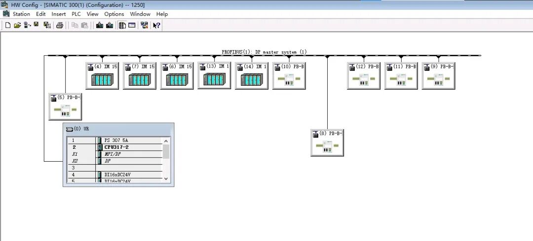
Since a physical DP interface of the PLC can only be configured as either a master or a slave, and cannot be reused, we need to establish an additional DP bus for communication with the newly added control system’s S7-1500 1513-1PN PLC with CP1542-5 Profibus-DP communication module as the DP master.
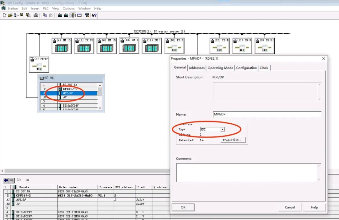
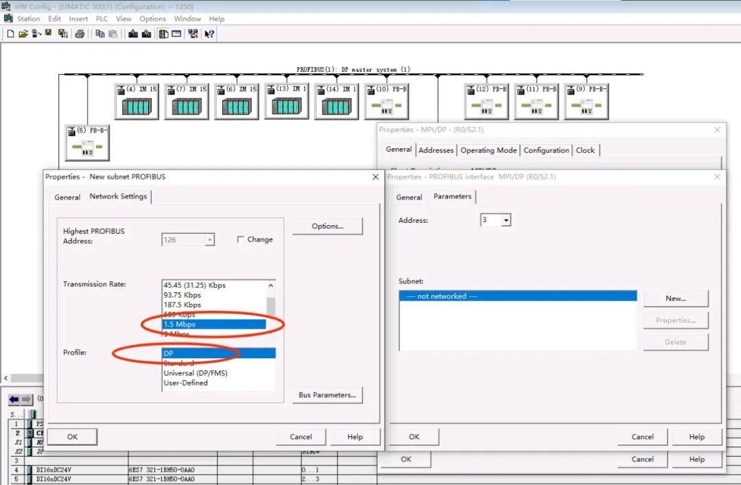
Double-click the S7-300 317-2DP PLC rack port “X1 MPI/DP”, and select “PROFIBUS” as the connection type. As shown in the figure below:
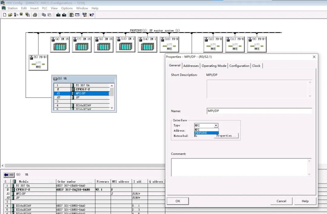
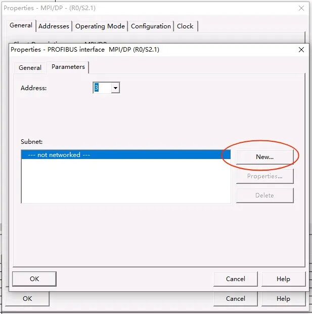
After selecting “PROFIBUS”, choose “New…” in the pop-up window, and in the secondary window, set the communication rate and bus configuration file type, then click “OK” in the secondary window to save (Note to record the communication rate parameter value, in this example 1.5Mbps). As shown in the figure below:
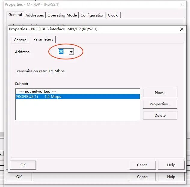
Set the DP slave address (note to record the slave address, in this example it is 20), and click “OK”. As shown in the figure below:
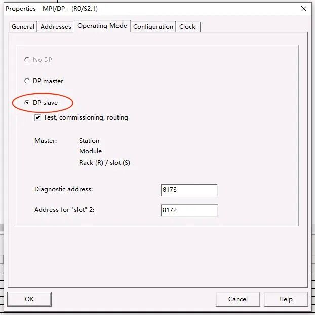
Select “Operating Mode” in the options bar, and choose “DP slave” for slave mode. As shown in the figure below:
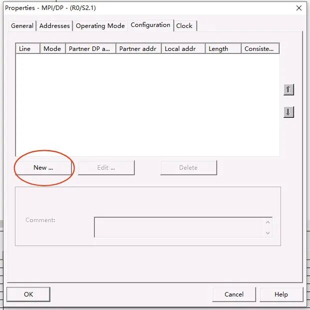
Next, select “Configuration” in the options bar, and click “New…” to configure the slave I/O addresses. As shown in the figure below:
First configure a 5-word long input area, click “OK”, and accept the assigned starting address. As shown in the figure below:
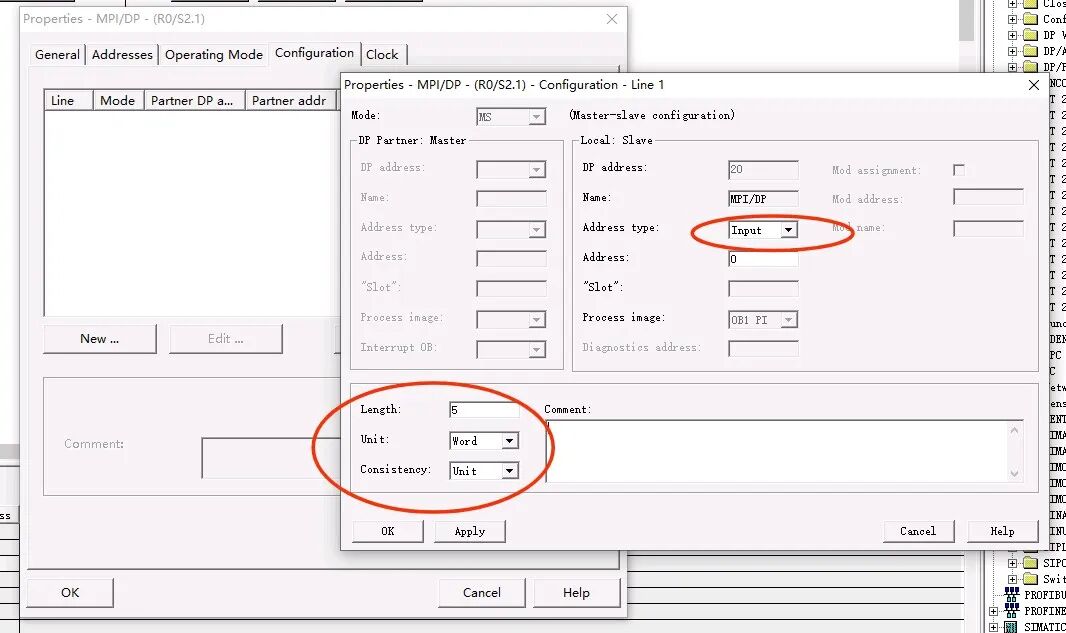
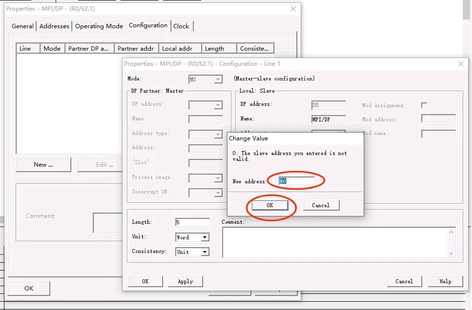
Then configure a 5-word long output area, click “OK”, and accept the assigned starting address. As shown in the figure below:
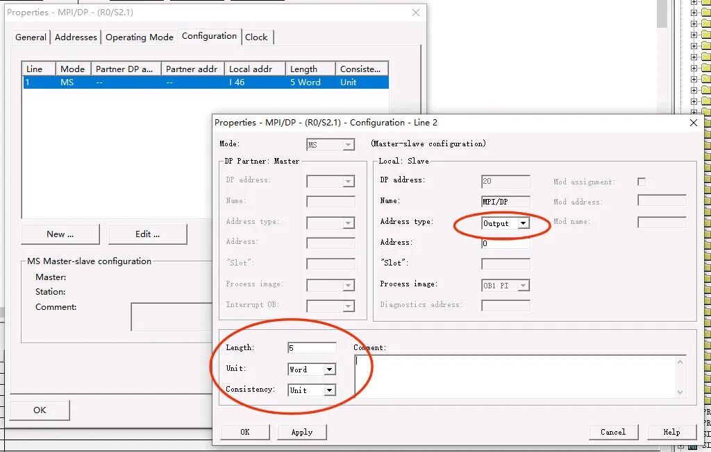
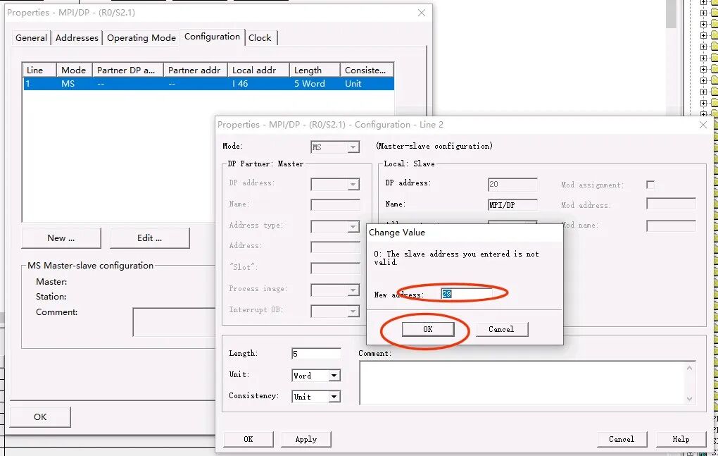
After completing the configuration of the slave I/O addresses, click “OK”. As shown in the figure below:
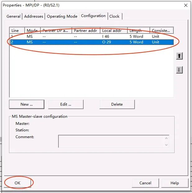
Save and compile the hardware configuration, thus completing the configuration on the S7-300 317-2DP PLC side.
The new control systemS7-1500 1513-1PN PLC with CP1542-5 Profibus-DP communication module as the DP master hardware configuration is shown in the figure below (TIA Portal V18 platform):
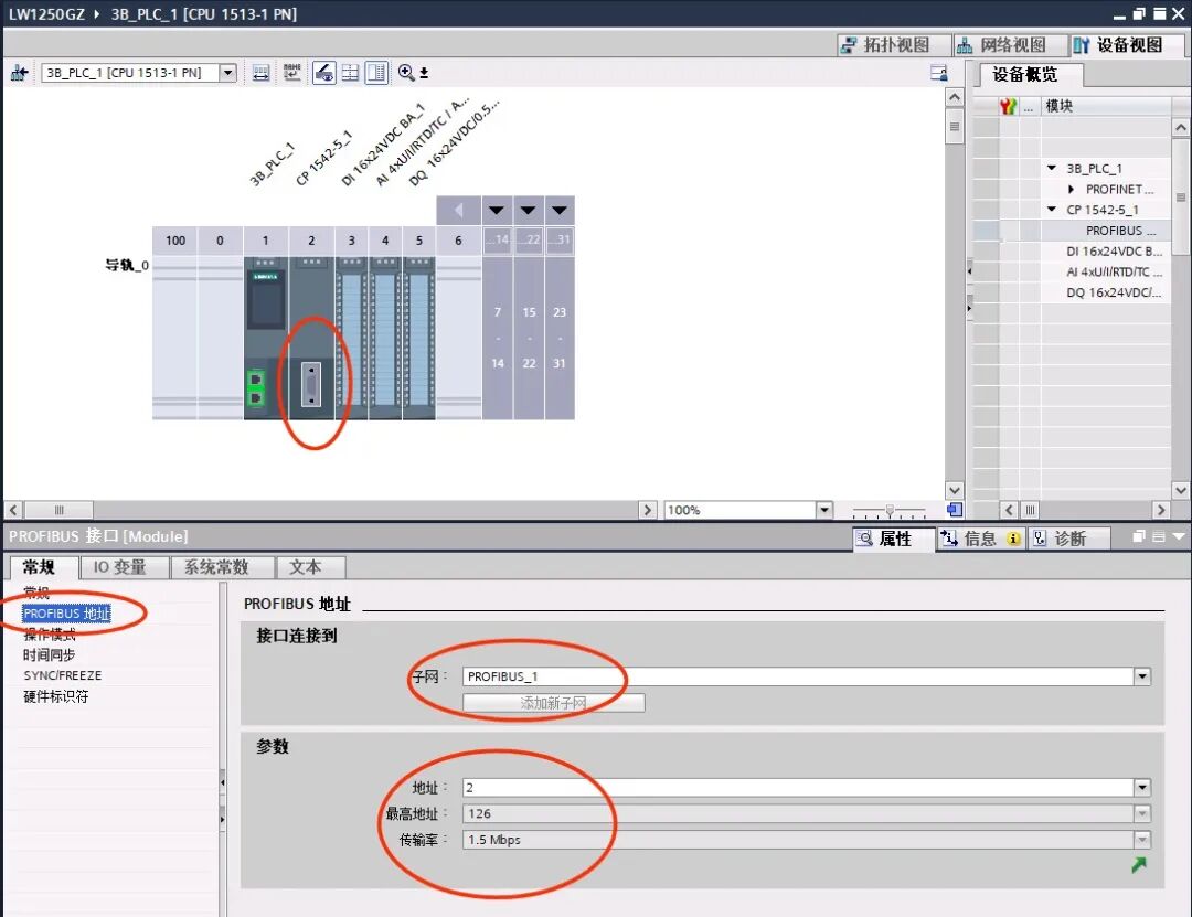
Note that the communication rate must be consistent with that on the S7-300 side.
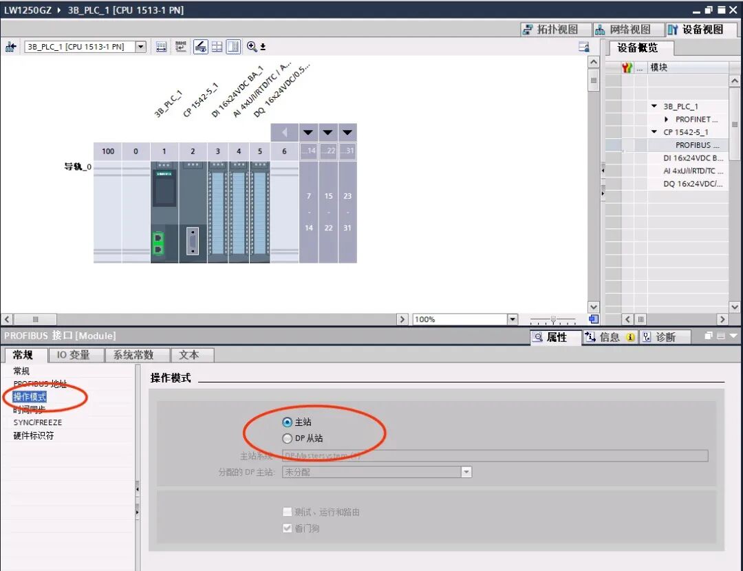
Select “Master” for the operating mode.
Note that the S7-300 317-2DP PLC mentioned in the network view refers to the slave module, not the controller. The GSD file for the slave must be installed for the S7-300 317-2DP PLC with order number 6ES7 317-2AJ10-0AB0 V2.1. As shown in the figure below:
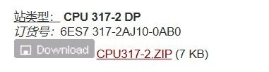
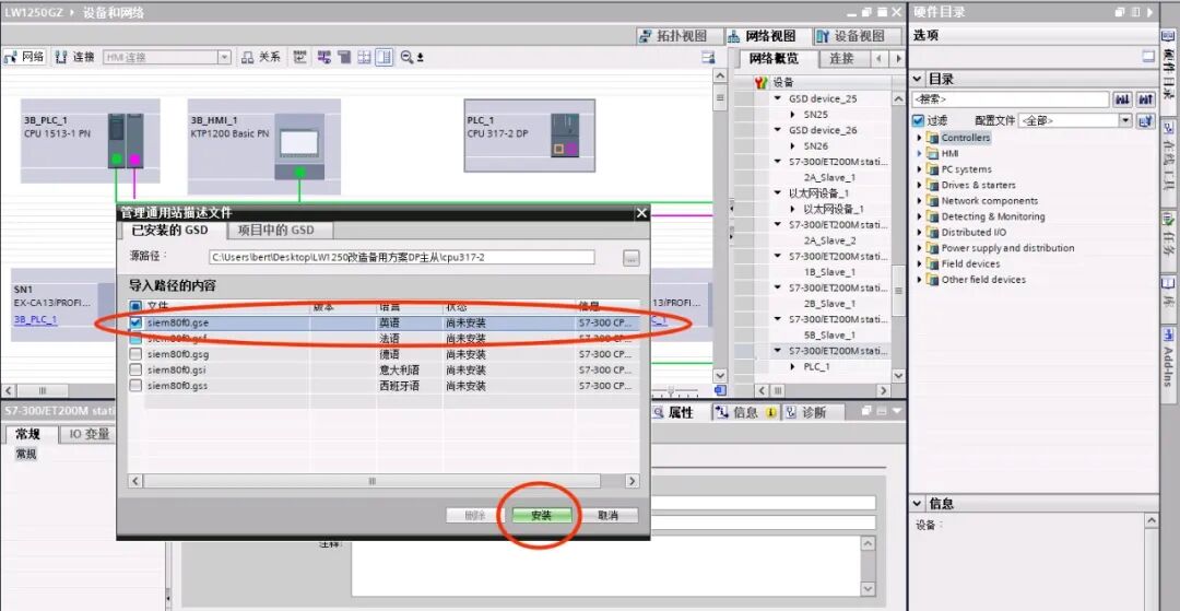
The download address for GSD files of other different types of slaves is:
https://support.industry.siemens.com/cs/document/113652/profibus-gsd-%E6%96%87%E4%BB%B6%EF%BC%9Asimatic?dti=0&lc=zh-CNSIEMENS
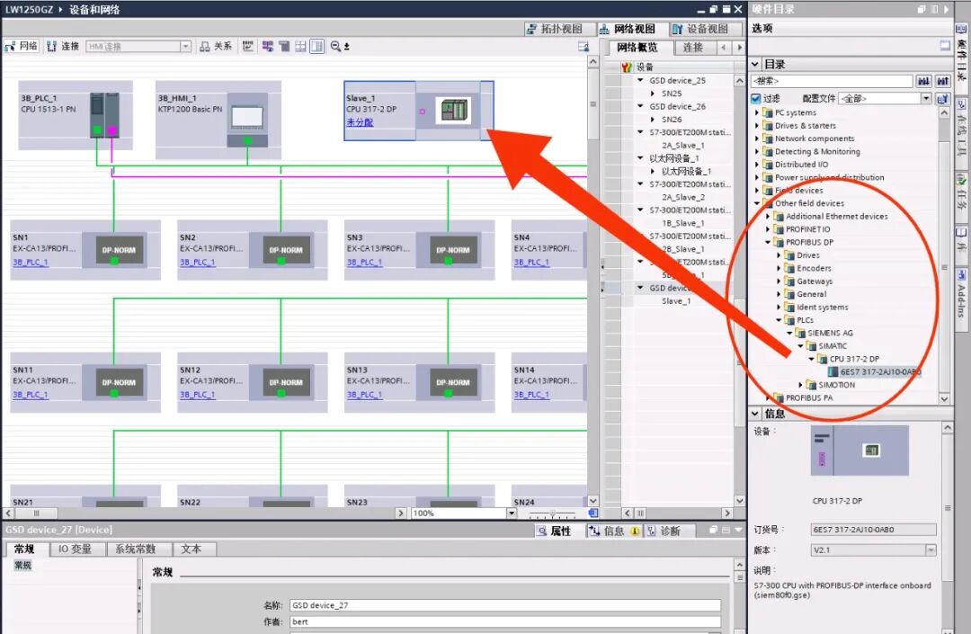
In the hardware directory, find the installed GSD file for the S7-300 317-2DP PLC slave, insert the slave, and assign it to the master system. As shown in the figure below:
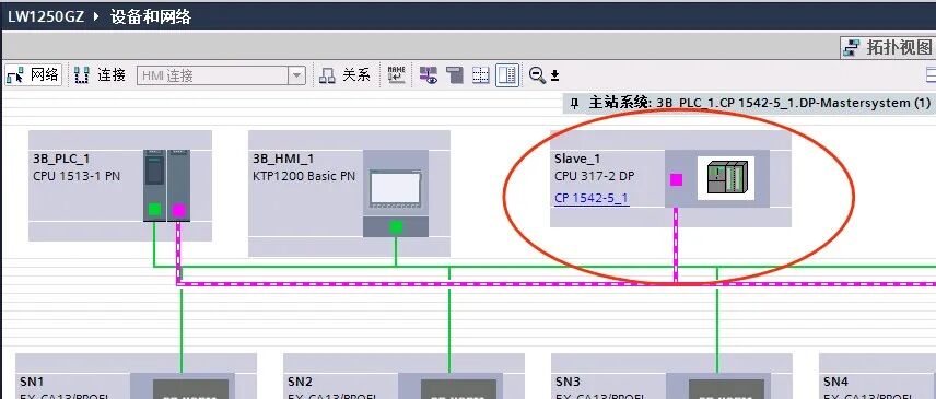
In the device identification view, double-click the DP interface to set the DP network parameters, ensuring consistency with the slave number and communication rate set in STEP7 SIMATIC Manager. As shown in the figure below:
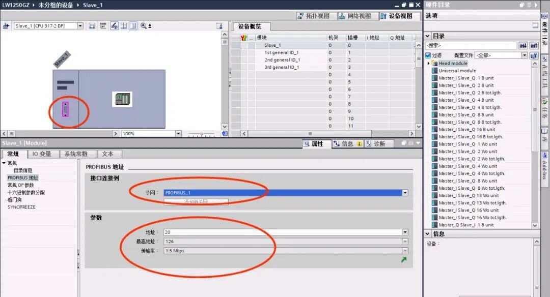
Insert the general module and configure the network I/O. Here, it is important to note that in STEP7 SIMATIC Manager, inputs are configured first, followed by outputs, while in TIA Portal, outputs are configured first, followed by inputs, forming a read-write crossover. Also, ensure that the word length and data type are consistent. As shown in the figure below:
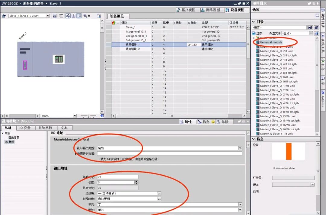
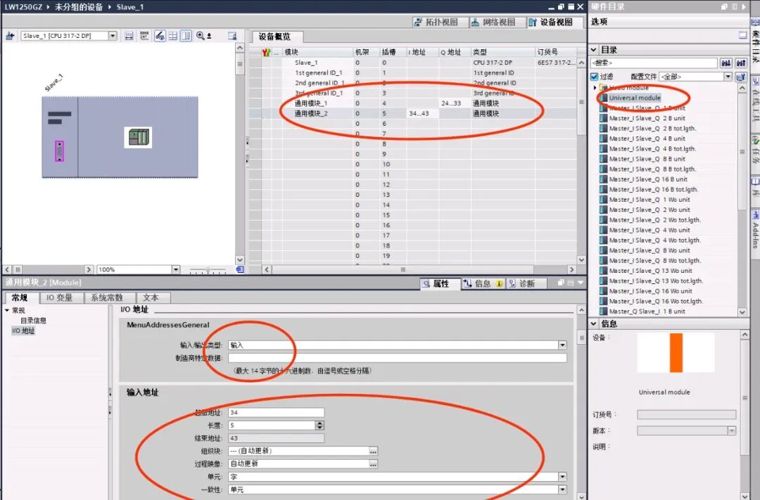
Once the configurations on both platforms are completed, the original PLC and the new PLC can be downloaded for read-write testing (Note the position of the terminal resistors). Due to space limitations, the testing process will not be elaborated here, but it is similar to the usage of a Coupler. If you have any questions, feel free to discuss in the comments section.
Feel free to like ❤️, share, and bookmark!
Follow me to enter a world of pure practical knowledge in industrial control!
Previous Articles
Disassembling the Tesla Model 3 Inverter: Simplicity is Optimal
How much do you know about terminal block knowledge points?
Why do electricians become more afraid of electricity the longer they work? These are the bitter tears in projects! Newcomers must be cautious~
Disassembling the Wuling Bingo 30kW Inverter: The materials used in vehicles starting from 50,000 yuan are also impressive
Surely no one is still unsure how to use a multimeter to test capacitors, right?

Share, view, and like, at least I want to have one!