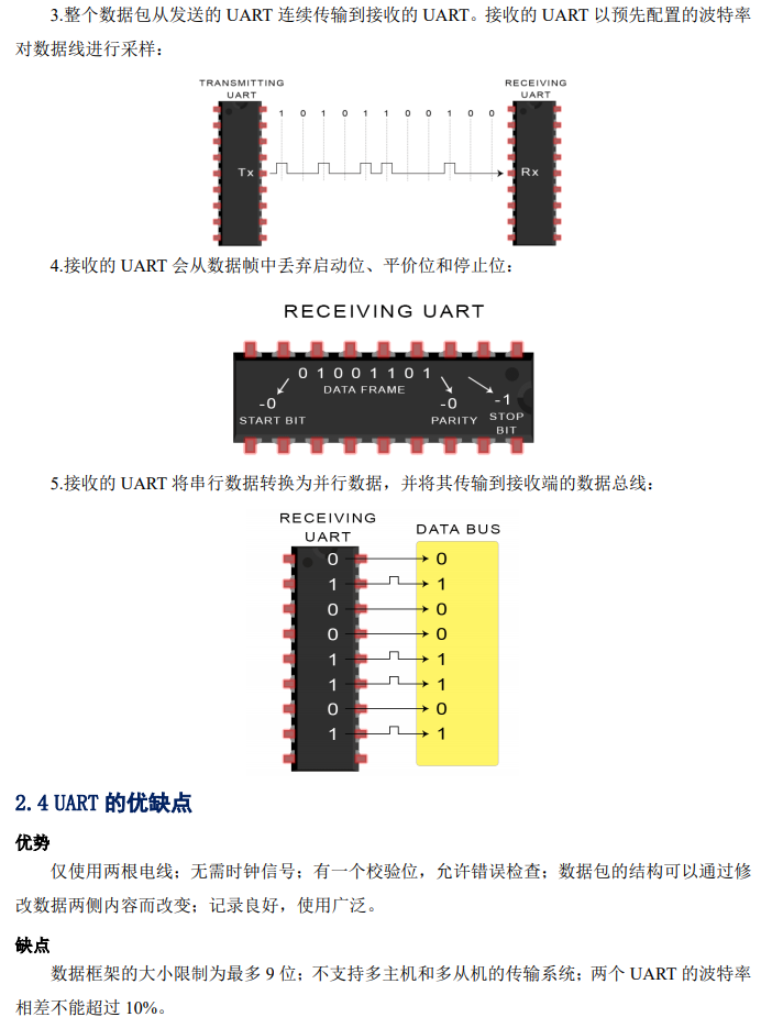
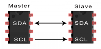
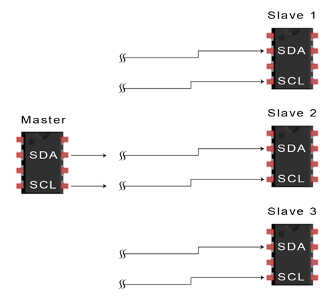
Comprehensive Guide to UART, SPI, and I2C Communication Protocols

Comprehensive Guide to UART, SPI, and I2C Communication Protocols

Comprehensive Guide to UART, SPI, and I2C Communication Protocols

Comprehensive Guide to UART, SPI, and I2C Communication Protocols

Comprehensive Guide to UART, SPI, and I2C Communication Protocols

Comprehensive Guide to UART, SPI, and I2C Communication Protocols

Comprehensive Guide to UART, SPI, and I2C Communication Protocols

Comprehensive Guide to UART, SPI, and I2C Communication Protocols

Comprehensive Guide to UART, SPI, and I2C Communication Protocols

Comprehensive Guide to UART, SPI, and I2C Communication Protocols

Comprehensive Guide to UART, SPI, and I2C Communication Protocols

I2C Communication Protocol Basics
3.1 Introduction to Communication
I²C (Inter-Integrated Circuit) is a serial communication bus designed by Philips in the early 1980s. It facilitates communication between motherboards, embedded systems, or mobile phones and peripheral devices. Due to its simplicity, it is widely used for communication between microcontrollers and sensor arrays, displays, IoT devices, EEPROMs, etc. It combines the best features of SPI and UART. Using I2C, you can connect multiple slaves to a single master (similar to SPI), and you can also allow multiple masters to control one or more slaves. This feature is particularly useful when you want multiple microcontrollers to log data to a single storage card or display text on a single LCD. Like UART communication, data is transmitted between devices using only two wires:
Comprehensive Guide to UART, SPI, and I2C Communication Protocols
SDA (Serial Data) – This line provides data sending and receiving functions for the master and slave.
SCL (Serial Clock) – This line is the clock signal line.
Like SPI, I2C is synchronous, meaning that the output of bits is synchronized to the sampling of bits by the clock signal shared between the master and slave. The clock signal is always controlled by the master.
Number of Wires Used
2
Maximum Speed
Standard Mode = 100kbps
Fast Mode = 400kbps
High Speed Mode = 3.4Mbps
Ultra Fast Mode = 5Mbps
Synchronous/Asynchronous
Synchronous
Serial/Parallel
Serial
Maximum Number of Masters
No Limit
Maximum Number of Slaves
1008
3.2 How It Works
Using I2C, data is transmitted in messages. Messages are broken down into data frames. Each message has an address frame that contains the binary address of the slave, along with one or more data frames containing the data being transmitted. The message also includes start and stop conditions between each data frame, read/write bits, and ACK/NACK bits:
Comprehensive Guide to UART, SPI, and I2C Communication Protocols
Start Condition: The SDA line switches from high to low before the SCL line switches from high to low.
Stop Condition: The SDA line switches from low to high after the SCL line switches from low to high.
Address Frame: Each slave has a unique 7-bit or 10-bit sequence that the master can use to identify the slave. If the master needs to send/receive data from the slave, it must first send the corresponding slave’s address, which will then match the address of the slave mounted on the bus.
Read/Write Bit: A single bit that specifies whether the master wants to send data (low) or request data from the slave (high).
ACK/NACK Bit: In a message, each frame is followed by an ACK (acknowledgment) or NACK (no acknowledgment) bit. If an address frame or data frame is successfully received, an ACK bit will be returned from the receiving device to the sending device.
3.3 Addressing
Unlike SPI, which has a slave chip select line, I2C needs another method to let the slave know that data is being sent to it, rather than another slave. It achieves this through addressing. The address frame is always the first frame after the start bit in a new message.
The master sends the address of the slave it wants to communicate with to each connected slave. Each slave then compares the address sent by the master with its own address. If the addresses match, it will return an ACK bit to the master by pulling the SDA line low. If the address does not match, the slave does nothing, and the SDA line remains high.
3.4 Read/Write Bit
The end of the address frame contains a single bit that notifies the slave whether the master wants to write data to it or receive data from it. If the master wants to send data to the slave, the read/write bit is low; if the master requests data from the slave, this bit is high.
3.5 Data Frame
After the master detects the ACK bit from the slave, the first data frame is ready to be sent.
Data frames are always 8 bits long and the most significant bit is sent first. Each data frame is immediately followed by an ACK/NACK bit to verify whether the frame was successfully received. Before sending the next data frame, the master or slave (depending on who sends data) must receive the ACK bit.
After all data frames have been sent, the master can send a stop condition to the slave to stop the transmission. The stop condition is when the SCL line transitions from low to high, and the SDA line transitions from low to high while the SCL line remains high.
3.6 Steps of I2C Data Transmission
1. The master sends a start condition to each connected slave by pulling the SDA line low before the SCL line transitions from high to low, triggering the start condition. This means giving the SDA line a falling edge while SCL is high, as shown in the diagram below, paying attention to the direction of the timing indicated by the arrows:
Comprehensive Guide to UART, SPI, and I2C Communication Protocols
2. The master sends the 7-bit or 10-bit address of the slave it wants to communicate with, along with the read/write bit:
Comprehensive Guide to UART, SPI, and I2C Communication Protocols
3. Each slave compares the address sent by the master with its own address. If the addresses match, the slave returns an ACK bit by pulling the SDA line low. If the master’s address does not match the slave’s address, the slave keeps the SDA line high (via a pull-up resistor). The slave that matches the address returns the ACK bit as shown in the diagram below:
Comprehensive Guide to UART, SPI, and I2C Communication Protocols
4. The master sends or receives data frames:
Comprehensive Guide to UART, SPI, and I2C Communication Protocols
5. After transmitting each data frame, the receiving device will return another ACK bit to the sender to confirm successful reception of the frame:
Comprehensive Guide to UART, SPI, and I2C Communication Protocols
6. To stop data transmission, the master sends a stop condition to the slave by pulling the SCL line high before pulling the SDA line high, which means giving the SDA line a rising edge while SCL is high, as shown in the diagram below, paying attention to the order of transmission indicated by the arrows:
Comprehensive Guide to UART, SPI, and I2C Communication Protocols
3.7 Single Master with Multiple Slaves
Using addressing, I2C allows a single master to control multiple slaves. Theoretically, using 7-bit addressing can provide 128 (2^7) unique addresses. Using 10-bit addressing is not common but can theoretically provide 1024 (2^10) unique addresses. To connect multiple slaves to a single master, connect them as shown below and use a 4.7K Ohm pull-up resistor to connect the SDA and SCL lines to Vcc:
Comprehensive Guide to UART, SPI, and I2C Communication Protocols
3.8 Multiple Masters with Multiple Slaves
Multiple masters can connect to a single slave or multiple slaves. In multi-master systems, issues arise when two masters attempt to send or receive data simultaneously via the SDA line. To solve this, each master must check whether the SDA line is low or high before transmitting a message. If the SDA line is low, it means another master is controlling the bus, and that master should wait to send the message. If the SDA line is high, it is safe to transmit the message.
To connect multiple masters to multiple slaves, connect them as shown below and use a 4.7K Ohm pull-up resistor to connect the SDA and SCL lines to Vcc:
Comprehensive Guide to UART, SPI, and I2C Communication Protocols
3.9 Advantages and Disadvantages of I2C
Advantages
Only two wires are required
Supports multiple masters and slaves
ACK/NACK bits confirm each frame is successfully transmitted
Hardware is less complex than UART
Well-known and widely used protocol
Disadvantages
Data transfer rate is lower than SPI
Data frame size is limited to 8 bits
Hardware required for implementation is more complex than SPI
3.10 Summary
The bus is composed of 9-bit blocks. Start condition: When SCL is high, SDA transitions from high to low, serving as the start condition. All slaves on the bus must start paying attention:
Comprehensive Guide to UART, SPI, and I2C Communication Protocols
The address bit follows the start condition as a 7-bit data frame, indicating the address of the slave the master wishes to communicate with:
Comprehensive Guide to UART, SPI, and I2C Communication Protocols
The read/write bit is the 8th bit following the 7-bit address: this bit indicates whether the master wants to read from or write to the slave: 1 indicates read; 0 indicates write.
Comprehensive Guide to UART, SPI, and I2C Communication Protocols
The synchronization bit between the master and slave: 0 indicates ACK; 1 indicates NACK. 0: I received it or data was received. 1: I did not receive it or data was not received.
Comprehensive Guide to UART, SPI, and I2C Communication Protocols
Data byte: The 8 bits after the address byte are the data byte from the master or slave. Whether it comes from the master or slave depends on the read/write bit. During the write cycle, the master sends data; during the read cycle, the slave sends data:
Comprehensive Guide to UART, SPI, and I2C Communication Protocols
Stop condition: When SCL is high, the rising edge generated by the SDA line transitioning from low to high serves as the stop condition, notifying the slave that the communication has ended.
Comprehensive Guide to UART, SPI, and I2C Communication Protocols
The complete bus protocol timing is shown in the diagram below:
Comprehensive Guide to UART, SPI, and I2C Communication Protocols
3.11 Notes
The arrows in the diagrams indicate the priority order of timing transmission; the arrows indicate the direction of data transmission or the timing that occurs first. The summary in 1.10 does not have arrows, with the left side representing the first occurring timing; please do not confuse it with the previous diagrams.
For a high-definition PDF file, please click to read the original text and download it from there.

-「END」-

Disclaimer: This account maintains a neutral stance on all original and reprinted articles’ statements and views; the articles pushed are for readers’ learning and exchange only. The copyrights of articles, images, etc., belong to the original authors. If there is any infringement, please contact for deletion.
Comprehensive Guide to UART, SPI, and I2C Communication Protocols
  • Did you know that the color of USB ports has meanings worth collecting!

  • Where is the gap between excellent engineers and average engineers?

  • Are electronic engineers in listed companies really impressive?

  • The mechanical hand of hardware engineers – a thorough review of the motion-sensing electric screwdriver ES15

  • Honestly! The salaries of hardware engineers are really too low!

  • Things hardware engineers must consider when changing jobs: HR loves to hear these reasons for leaving!

Leave a Comment