-
Basic Theoretical Knowledge
i. Parallel Communication/Serial Communication
ii. Asynchronous Communication/Synchronous Communication
iii. Half-Duplex Communication/Full-Duplex Communication
i. Parallel Communication/Serial Communication
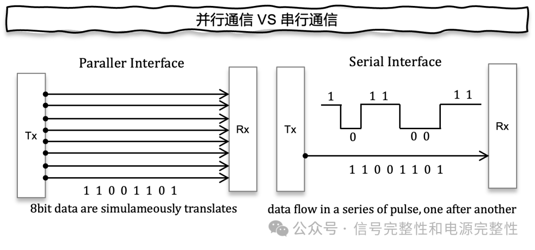
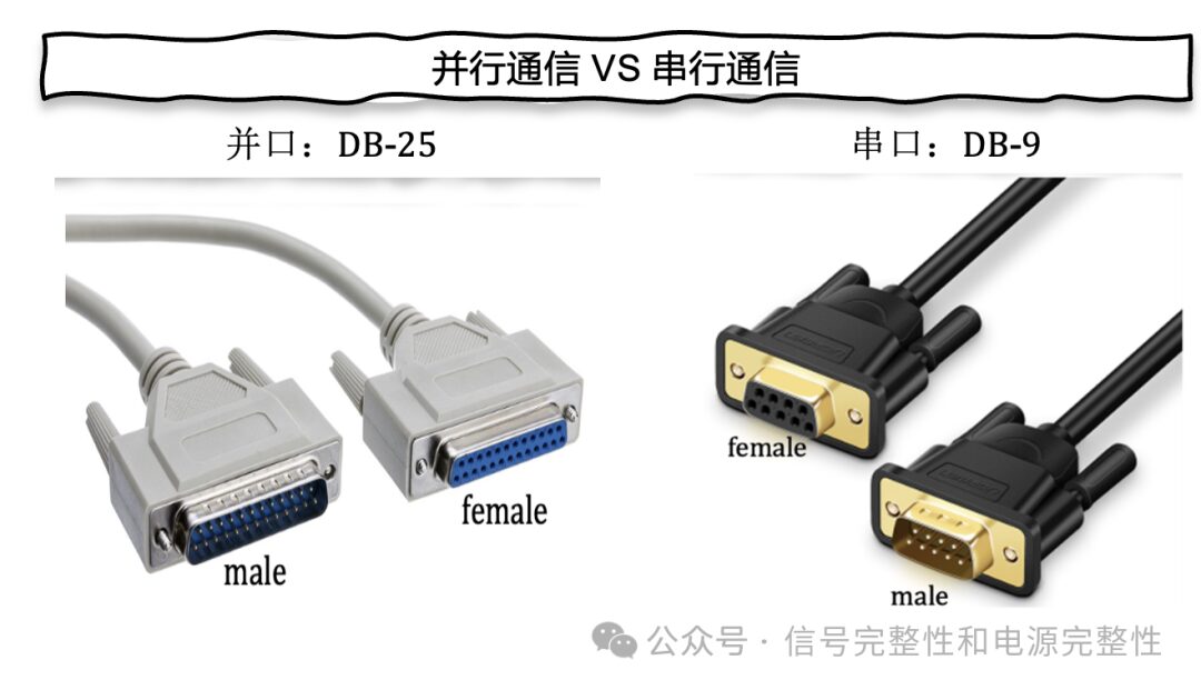
Parallel communication: Fast transmission speed, transmitting 8 bits at once, but high communication costs, requiring 8 independent channels. It does not support long-distance transmission. Used in devices such as printers and scanners, for example, the DB-25 interface.
Serial communication: Slow transmission speed, low cost, supports long-distance transmission, and is the main method of computer communication, such as the DB interface.
ii. Asynchronous/Synchronous Communication
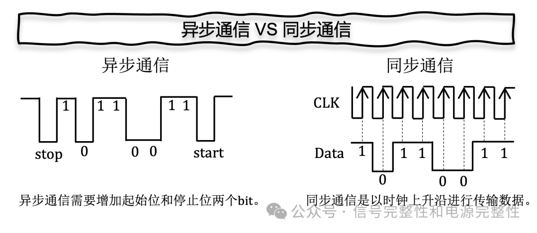
Asynchronous communication: Used for low-speed devices, which may have a higher error rate.
Synchronous communication: Used for high-speed device transmission, where data is transmitted with a synchronized clock as a timing reference.
iii. Half-Duplex/Full-Duplex Communication
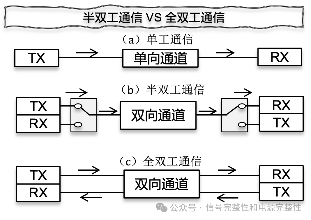
Simplex communication: The transmitter can only send data to the receiver, not allowing transmission from the receiver back to the transmitter.
Half-duplex communication: The transmitter and receiver can read and write to each other, but cannot do so simultaneously.
Full-duplex communication: The transmitter and receiver can read and write to each other simultaneously.
-
I2C, UART, and SPI Interfaces
i. UART Interface
UART (Universal Asynchronous Receiver Transmitter) features serial communication, asynchronous communication, and full-duplex communication, using a two-wire system (TX, RX), with slow transmission speed and point-to-point asynchronous communication, generally used in RJ45 Consoles, printers, etc.
ii. I2C Interface
I2C (Inter-Integrated Circuit) features serial communication, synchronous communication, and half-duplex communication, using a two-wire system (SDA, SCLK), used in monitoring, storage, and digital signal processing applications.
iii. SPI Interface
SPI (Serial Peripheral Interface) features serial communication, synchronous communication, and full-duplex communication, using a four-wire system (CS, SCLK, MOSI, MISO), with fast transmission speed and precise synchronization, generally used in memory, digital signal processing, sensors, and voice recognition applications.

i. UART Interface

UART working principle:
The transmitter UART1 receives parallel data from the sending data bus, adds start bits, parity bits, and stop bits to the data frame, packaging it into a data packet; then sends the data packet serially to the receiver UART2; UART2 samples the data at a pre-configured baud rate, restoring the data packet back into a data frame; finally, UART2 transmits the data frame serially to parallel to the receiving data bus.
ii. I2C Interface
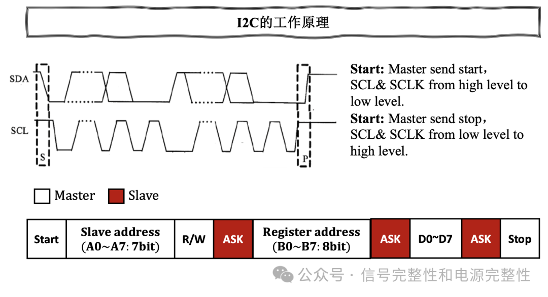
Step 1: When the I2C bus is idle, pull-up resistors pull SDA and SCLK to high level.
Step 2: The Master sends a start signal, switching SDA from high to low, then SCLK line also switches from high to low.
Step 3: The Master then sends the slave’s address and the read/write command, where write is 0 and read is 1. The slave responds to the master with an ACK after receiving the address and read/write command.
Step 4: The Master, after receiving the ACK, sends the address of a specific register, and the slave replies with an ACK after receiving it.
Step 5: The Master sends 8-bit data to the specific register again after receiving the ACK, and the slave replies with an ACK after receiving the data, repeating this action until all data is sent.
Step 6: The Master receives a stop signal, SCLK switches from low to high, and then SDA also switches from low to high.
iii. SPI Interface
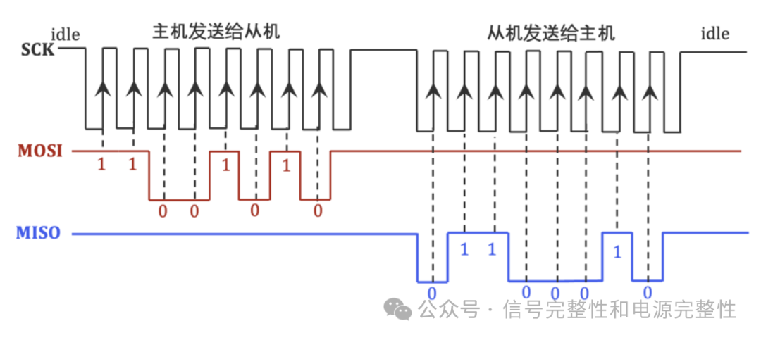
SPI is a four-wire serial bus that includes CS, SCK, MOSI, and MISO signals.
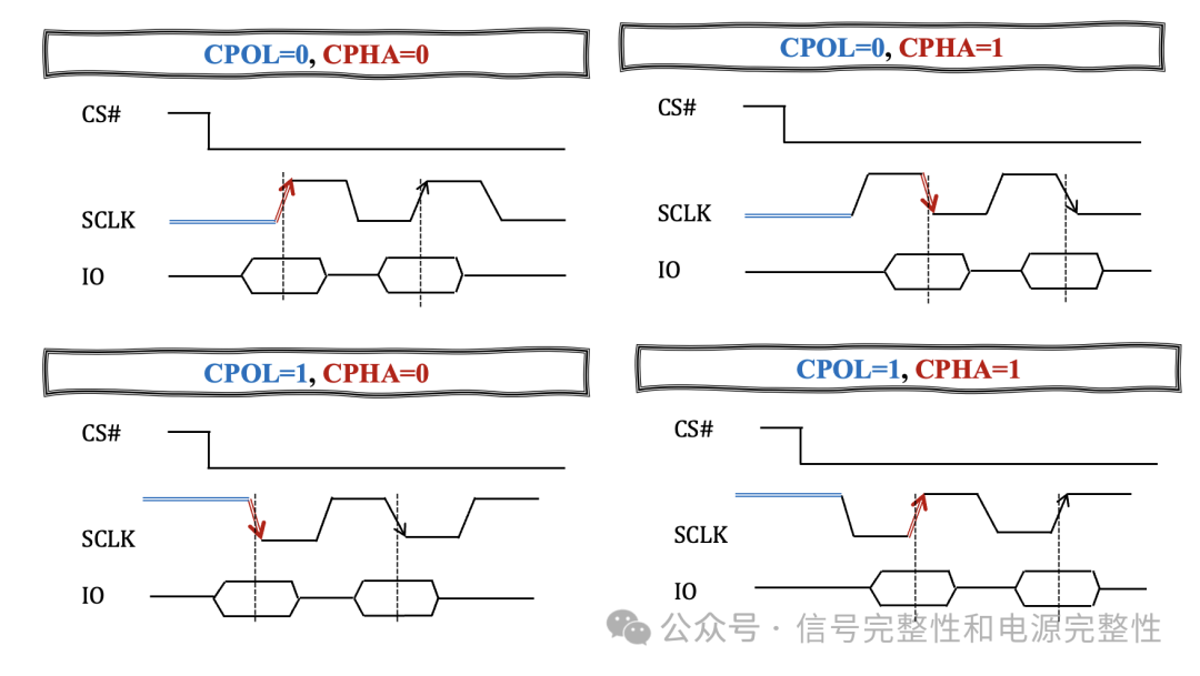
Clock Polarity: Clock Polarity (CPOL) can be idle or communication state; CPOL=1 means the clock is high when idle; CPOL=0 means the clock is low when idle.
Clock Phase: Clock Phase (CPHA) requires a certain time for data to stabilize from generation; if the Master samples on the rising edge, then the Slave can only sample on the falling edge. CPHA=1 indicates data sampling occurs on the first clock edge, determined by CPOL whether it’s the rising or falling edge; CPHA=0 indicates data sampling occurs on the second clock edge.