Read the latest documentation and participate:【Find Errors in Documentation to Win Prizes】 Event
For the latest documentation content, see:

1. Introduction
The I2C bus (Inter-Integrated Circuit) is a simple, bidirectional, two-wire synchronous serial bus developed by Philips. It requires only two wires to transmit information between devices connected to the bus.
The Air724UG module provides 2 I2C interfaces, supporting speeds of FAST (400KHz), SLOW (100KHz), and 3500KHz. Peripheral addresses support 0x00-0x7f.
1.1 Features
-
Supports Fast mode (400Kbps) and Slow mode (100Kbps)
-
Only supports I2C master mode
-
Internal pull-up resistors can be configured via software, 1.8K or 20K
-
The module supports a maximum of 2 independent I2C interfaces
-
Theoretically supports up to 127 slave devices
1.2 Module I2C Function List
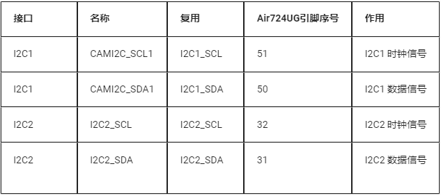
Note: Please prioritize using I2C2; I2C1 is reserved for camera use.
2. Overview of Demonstration Functionality
This tutorial teaches you how to use the Air724 development board to demonstrate I2C functionality, read temperature and humidity from the AHT10 digital temperature and humidity sensor, and observe experimental results through logs.
3. Preparing the Hardware Environment
3.1 Development Board Preparation
Use the EVB_Air724 development board, as shown in the figure below:
For detailed instructions on using this development board, refer to: https://docs.openluat.com/air724ug/product/
In the Air724UG product manual, see the “EVB_Air724UG_AXX Development Board User Guide”; the latest version of the user guide at the time of writing this article is: “EVB_Air724UG_A14 Development Board User Guide”; if you encounter any issues during the use of the development board, you can directly refer to this user guide.
API: https://doc.openluat.com/wiki/21?wiki_page_id=2068
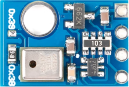
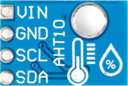
3.2 AHT10 Module
AHT10 digital temperature and humidity sensor module
3.3 Data Communication Line
One USB data cable (micro USB).
3.4 PC Computer
Windows 7 and above versions of Windows.
3.5 SIM Card
A SIM card that can access the internet in mainland China. Generally, using IoT cards or mobile cards from China Mobile, China Telecom, or China Unicom is acceptable.
3.6 Assembling the Hardware Environment
Insert the USB data cable into the USB port, connect the other end to the computer, set all DIP switches to ON, select UART1 for the serial switch, set the USB power switch corresponding to 4V to ON, and lock the SIM card into the SIM card slot, as shown in the figure below.

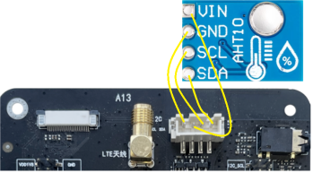
3.7 Connecting the Mainboard and Sensor
Ensure that SDA, SCL, GND, and VIN are connected between the mainboard and the sensor, as shown in the figure below.
4. Preparing the Software Environment
4.1 Download Debugging Tools
Refer to the instructions:
Luatools download and detailed usage: https://docs.openluat.com/Luatools/
4.2 Source Code and Firmware
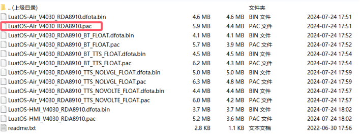
1. Download the low-level core
Download the low-level firmware and unzip it
Link: https://docs.openluat.com/air724ug/luatos/firmware/
As shown in the figure below, the red box indicates what we need to use.
2. The demo used in this tutorial:
https://gitee.com/openLuat/LuatOS-Air724UG/tree/master/script_LuaTask/demo/peripheral/%E6%B8%A9%E6%B9%BF%E5%BA%A6%E4%BC%A0%E6%84%9F%E5%99%A8/AHT10
4.3 Downloading Firmware and Scripts to the Development Board
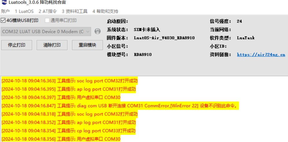
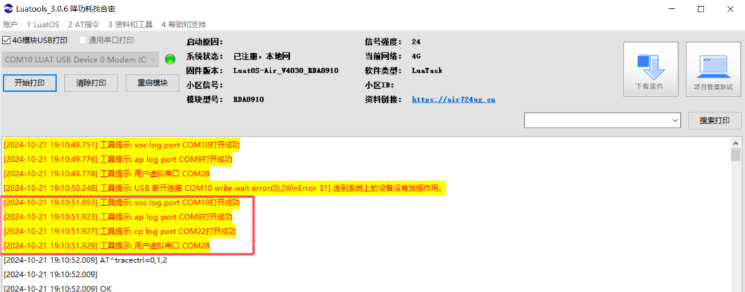
Open Luatools, power on the development board, and if the boot is successful, Luatools will print the following information.
Click on project management test options.
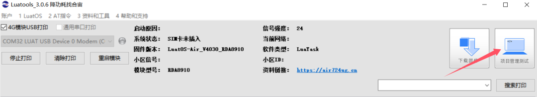
Enter the management interface, as shown in the figure below.
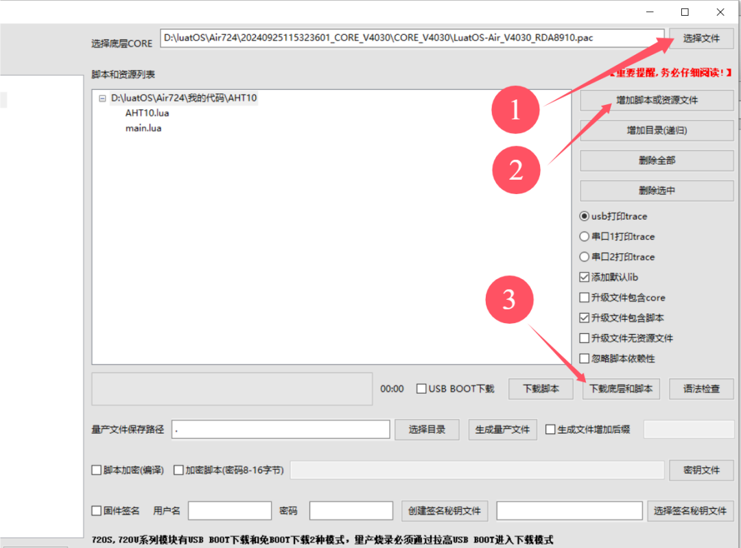
-
Click select file, choose the low-level firmware; my file is located in D:\luatOS\Air724 path

-
Click to add scripts or resource files, select the previously downloaded program source code, as shown in the figure below.
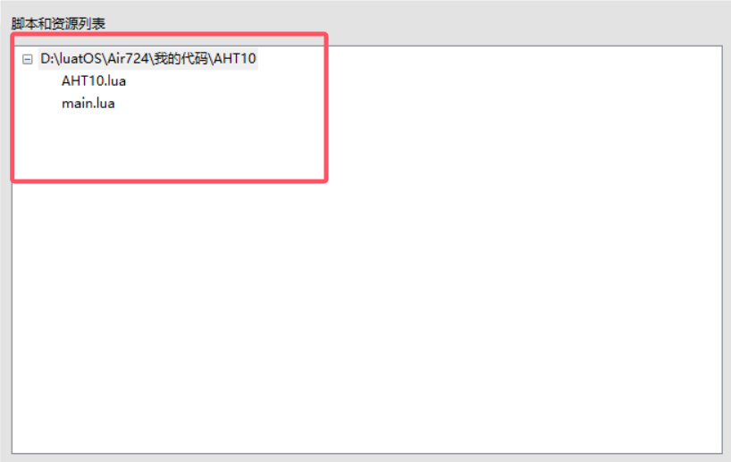
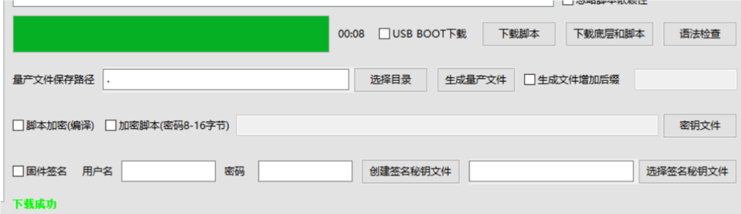
-
Click to download the low-level and script, the download is completed as shown in the figure below.
5. Introduction to Code Examples
5.1 API Description
5.1.1 i2c.setup( id, speed [,slaveaddr] [,isbaud] [,reg16bit])
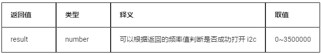
Open the i2c interface
Parameters
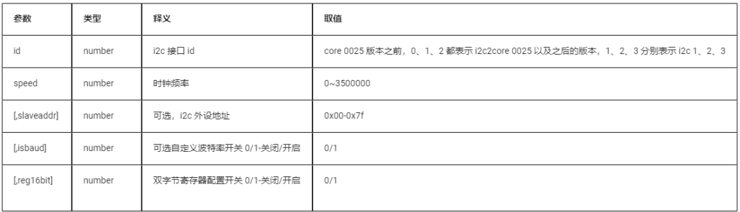
Return Value
Example
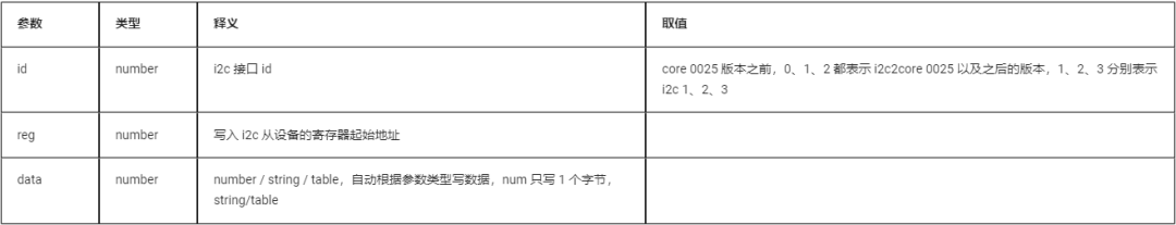
5.1.2 i2c.write( id, reg, data )
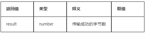
Transmit data to the specified register address reg
Parameters
Return Value
Example
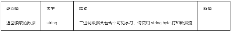
5.1.3 i2c.read( id, reg, num )
Read the data content of the specified register address reg
Parameters
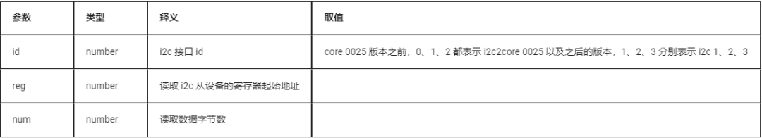
Return Value
Example
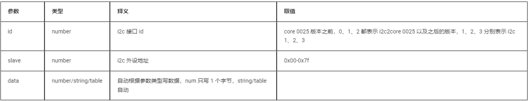
5.1.4 i2c.send( id,slave, data )
Write data to the slave device
Parameters
Return Value
Example
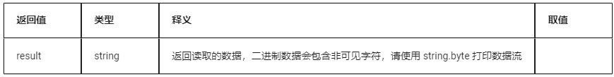
5.1.5 i2c.recv( id, slave,size )
Read data from the slave device
Parameters
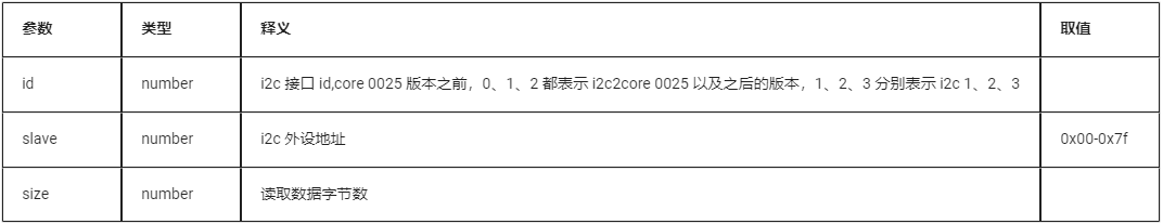
Return Value
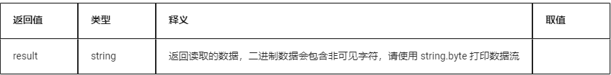
Example
5.1.6 i2c.close( id )
Close the I2C interface
Parameters
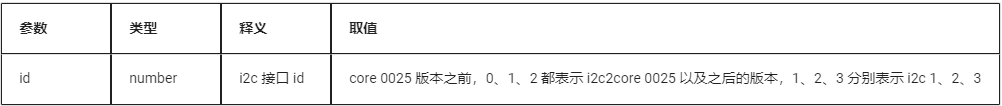
Return Value
None
5.2 AHT10.lua Code
Open the AHT10 sensor, read the temperature and humidity registers, interpret the temperature and humidity data, and print logs.
5.3 main.lua Code
This code is the main program script; after the system starts, it will first configure the 4G network, wait for the network connection to succeed, and then load the test module.
6. Boot Debugging
6.1 Powering on the Development Board
After connecting the hardware and downloading the firmware, start the Luatools software; the system running information will be displayed on the interface. The red box shows the normal printed information after the development board is connected to the PC, as shown in the figure below.
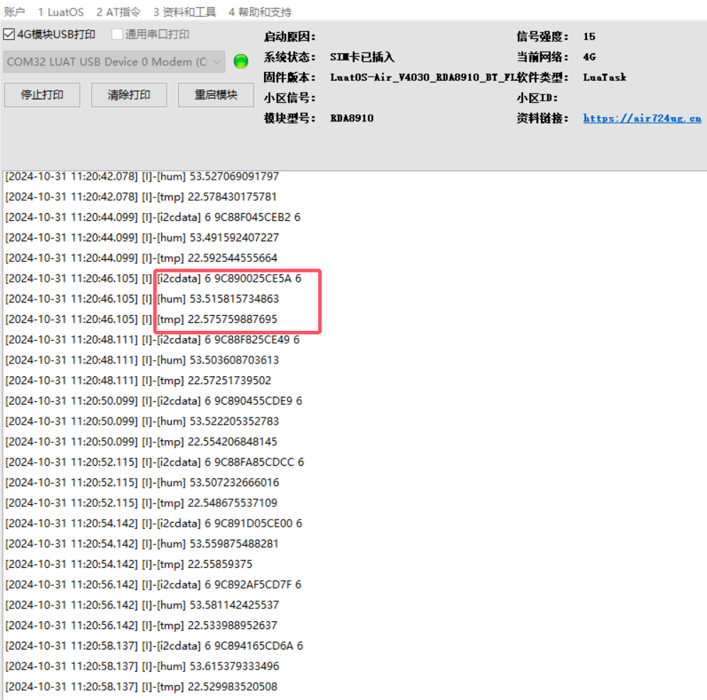
6.2 Function Debugging
The system continuously prints temperature and humidity data.
7. Common Questions
7.1 Does I2C need to be set up each time before reading or writing data?
No, it is not necessary.
The normal business logic is:
i2c.setup
… You can read and write data multiple times here
i2c.close
After setup, as long as it is not closed, you can repeatedly read and write data.
Once close is executed, you must set up again before reading or writing data next time.
7.2 Can the module act as a slave device during I2C communication?
Note: The module I2C can only act as a master device, and external pull-up is required; when configuring for FAST speed, the pull-up resistor value should not exceed 4.7K.
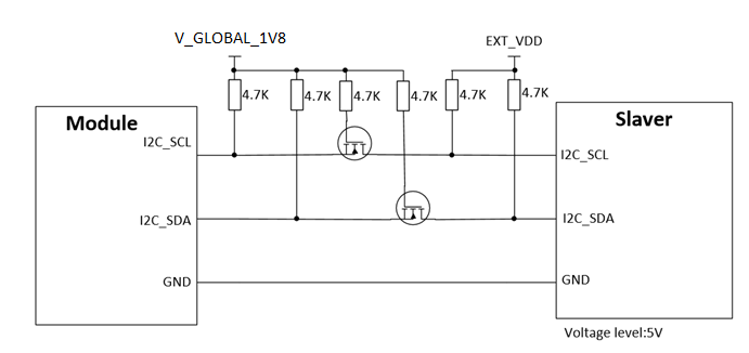
7.3 If the levels of the master and slave devices are different during I2C communication, do I need to perform level conversion?
If the reference levels of the master and slave devices are inconsistent, please pay attention to perform level conversion. As shown in the figure:
7.4 If the I2C device’s 7-bit address is 0x38, do I need to manually convert it to an 8-bit address?
Here, the i2c_addr address is a 7-bit address;
If the I2C peripheral manual provides an 8-bit address, you need to right shift the 8-bit address by 1 bit and assign it to the i2c_addr variable;
If the I2C peripheral manual provides a 7-bit address, you can directly assign the 7-bit address to the i2c_addr variable.

▼ Contact the Marketing Director of Hezhou ▼

Scan the QR code to add friends on WeChat/Enterprise WeChat
▼ Learn more about Hezhou News ▼
Tugger & Hezhou strategic cooperation empowers the Cat.1 module to go overseas with low power consumption testing tool – Hezhou Power Analyzer
Charging at 2 microamps! The development history of Hezhou’s low power consumption