
Follow “Chipown Microelectronics” ↑ Only Original Technical Content
Currently, the application of stepper motors in home appliances and smart devices requires achieving more flexible motor control, safer motor protection, and advanced diagnostic functions at a lower system cost. As the number of end products using stepper motors increases, additional peripheral IO expansion is needed, leading to increased system costs.
Chipown recommends the powerful PN7716 stepper motor driver chip (dual-channel H-bridge) to all engineers! PN7716 can achieve cascading multiple motor drivers through a single I2C communication bus, greatly reducing the number of control IOs and providing flexible control mode selection, detailed fault diagnostics, and enhanced protection functions. This not only reduces the number of system peripheral components, lowers system costs, and reduces size but also makes the system smarter.
Highlights of PN7716
01.
I2C Interface Cascading Control
Connect the SCL and SDA pins of multiple PN7716 slave devices together, then connect them to the I2C interface of the master device MCU to control multiple PN7716 slave devices through a single I2C communication bus, as shown in Figure 1.
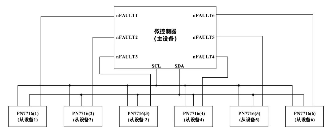
Figure 1 PN7716 Drive: Only 8 IO Ports Required
For example, to drive 6 stepper motors, when comparing the PN7716 with the standard stepper driver PN7715 (Figure 2) that has an I2C interface, the PN7716 solution only requires 8 IO ports, while the PN7715 solution requires 24 IO ports, which is three times that of the former. Therefore, using the I2C cascading control of PN7716 for multiple stepper motors greatly saves the required MCU control pins, reducing system costs and area.
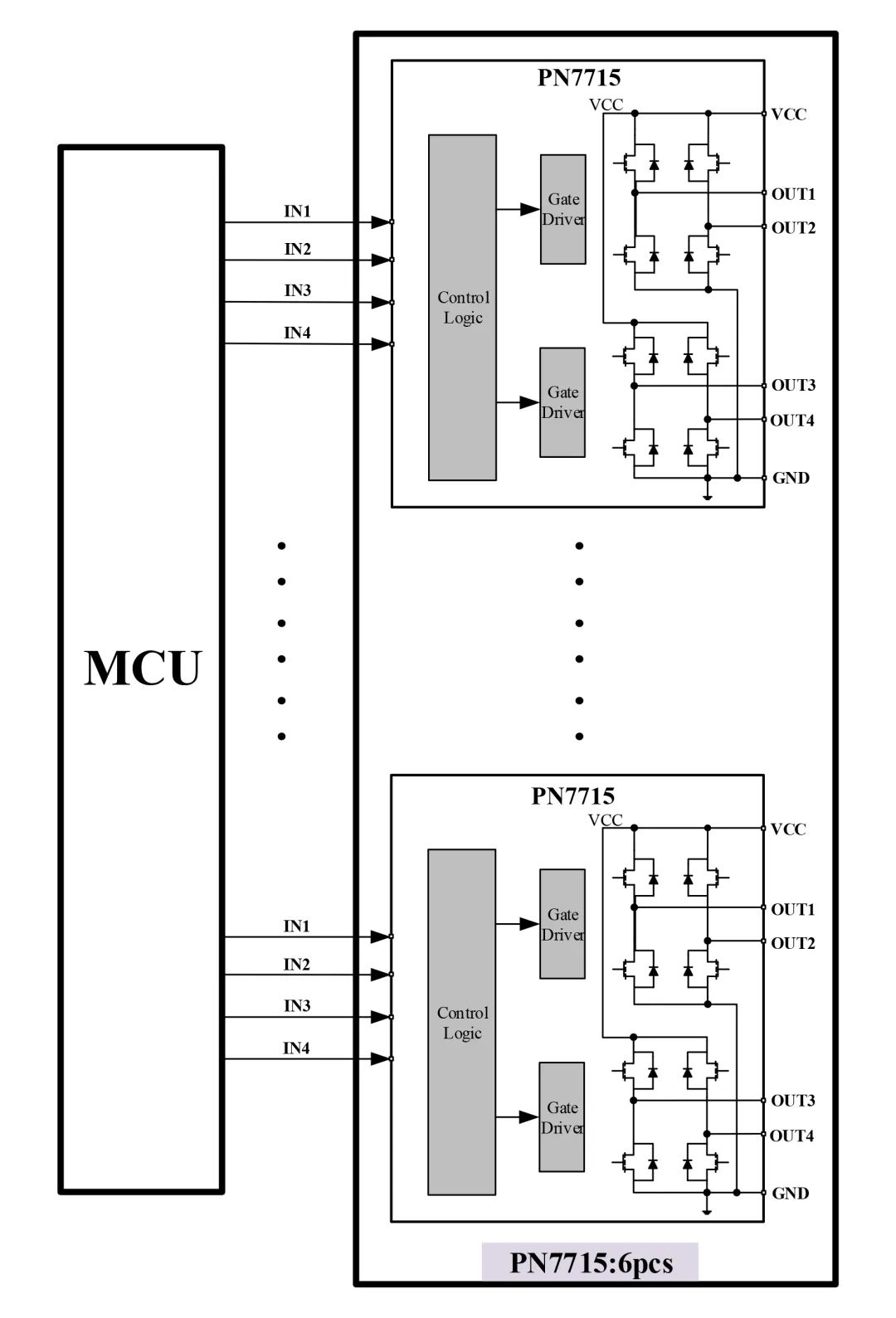
Figure 2 PN7715 Drive: Requires 24 IO Ports
02.
Multiple Control Interfaces Available
The PN7716 can select multiple control modes by configuring the I2C registers, allowing users to choose based on actual applications.
4-Pin Interface
Drives one stepper motor; can also drive two brushed DC motors, achieving full functionality;
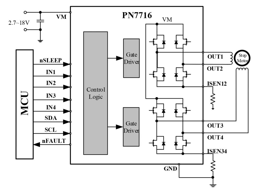
Figure 3 4-Pin Drives One Stepper
2-Pin Interface
Drives one stepper motor: full-step operation; can also drive two brushed DC motors: Compared to the 4-pin mode, it saves two MCU interfaces;
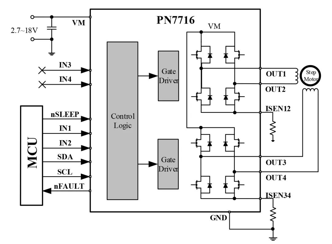
Figure 4 2-Pin Drives One Stepper
Parallel Bridge Interface
Used to drive one brushed DC motor, provides double the continuous current (2A);
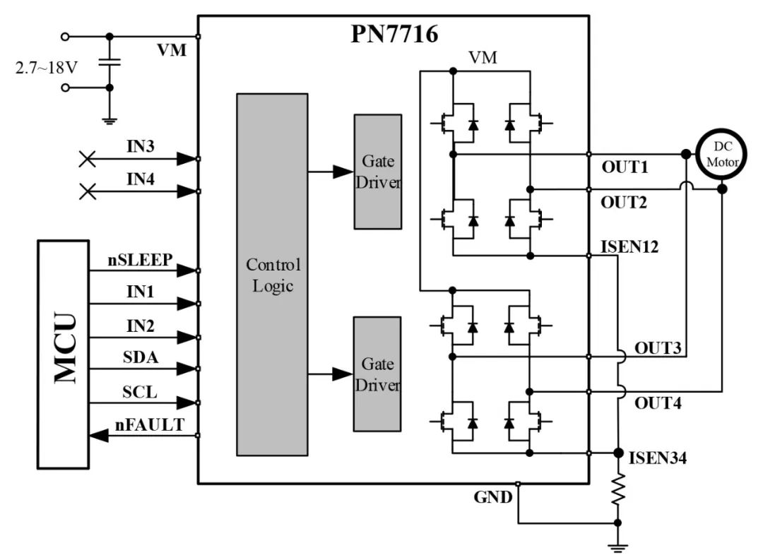
Figure 5: Parallel Bridge Mode Driving a Brushed DC Motor
Independent Bridge Interface
Provides 4 independent half-bridge drives, outputting two states: upper switch on, connected to VM; lower switch on, connected to GND.
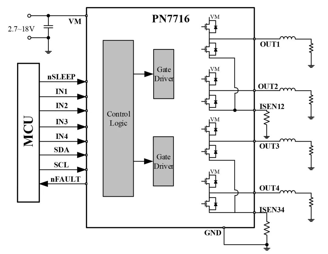
Figure 6 Independent Bridge Mode Drive
03.
Fault Protection and Diagnostics
The PN7716 integrates protection functions such as undervoltage (UVLO), over-temperature (OTP), output over-current (OCP), and output open-circuit detection (OLD). The MCU can read the internal error status register via I2C for detailed fault diagnostics and then perform corresponding control, among which the OLD open-circuit detection function is a very powerful and useful diagnostic feature.
Open-circuit detection takes effect when the chip exits sleep mode or powers on. By configuring the control register, it can also be set for open-circuit detection at any time; the OLD function can be divided into the following three types based on the OUT load connection method (taking a single-phase H-bridge OUT1, OUT2 as an example):
a. OUT1 and OUT2 Indirect Load:
As shown in Figure 7, when the PN7716 powers on, the internal SW1_HS and SW2_LS are closed, and current flows from AVDD through OUT1, the load, to OUT2, GND. By detecting the internal corresponding resistance voltage divider, when the OL comparator outputs high and the path current is less than the set value, it determines an output open circuit;
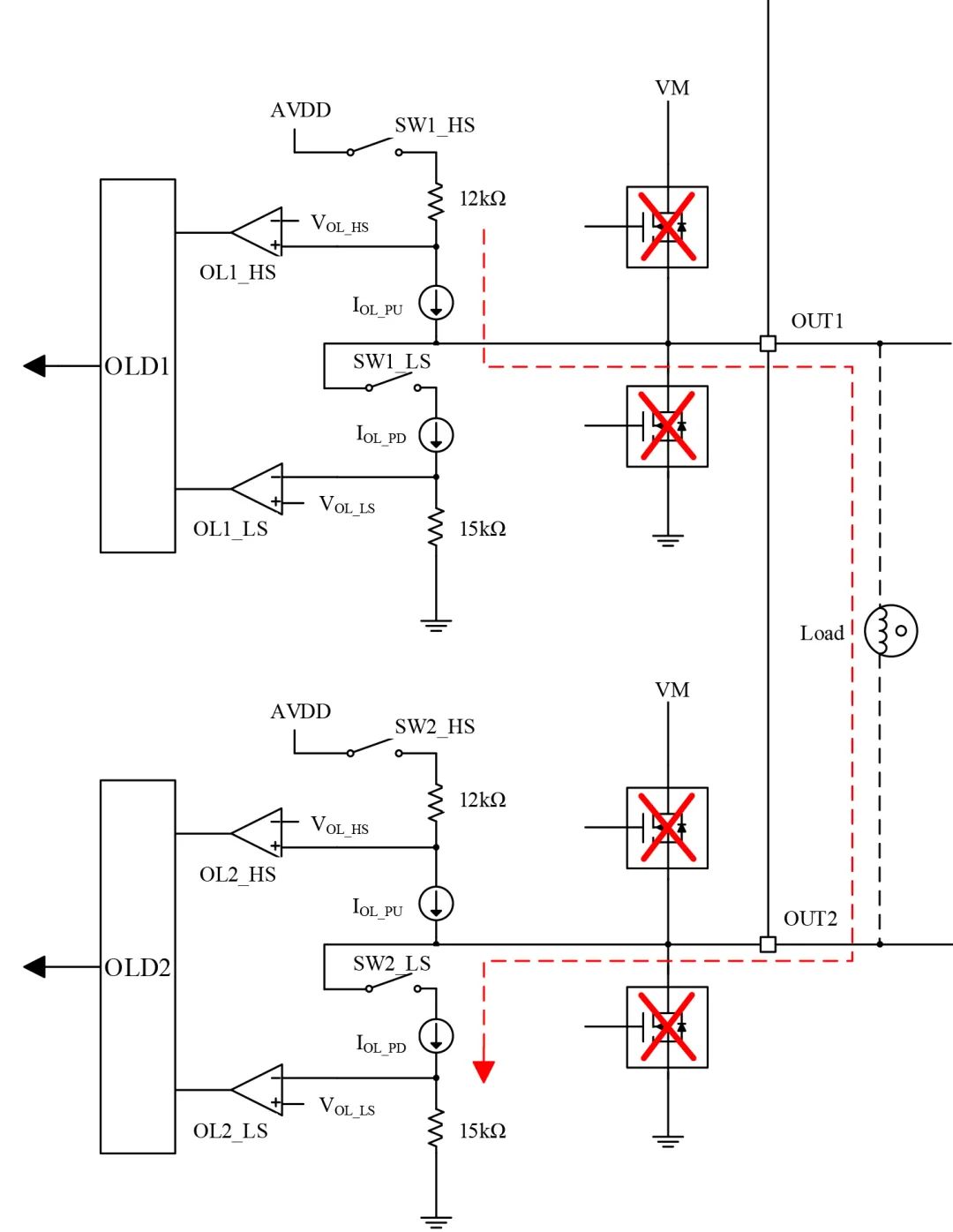
Figure 7 Open-Circuit Detection in Full Bridge Connection
b. OUT1 and VM Indirect Load:
As shown in Figure 8, when the PN7716 powers on, the internal SW1_LS is closed, and current flows from VM through the load, OUT1, to the internal GND. By detecting the internal corresponding resistance voltage divider, when the OL comparator outputs high and the path current is less than the set value, it determines an output open circuit;
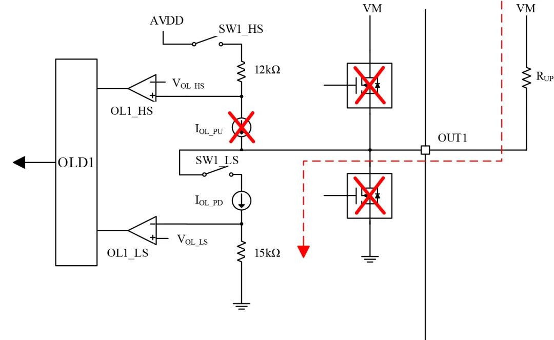
Figure 8 Open-Circuit Detection with Load Connected to VM
c. OUT1 and GND Indirect Load:
As shown in Figure 9, when the PN7716 powers on, the internal SW1_HS is closed, and current flows from AVDD through OUT1, the load, to GND. By detecting the internal corresponding resistance voltage divider, when the comparator outputs high and the path current is less than the set value, it determines an output open circuit;
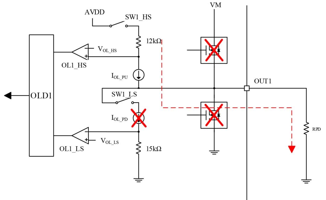
Figure 9 Open-Circuit Detection with Load Connected to GND
Introduction to PN7716 Performance and Comparison with Competitors
Main Features
01

Figure10 PN7716 Pinout Diagram
♢ Wide voltage range: 2.7V~18V
♢ Low on-resistance: 0.7Ω (HS+LS)
♢ Single-channel 1A continuous current, parallel 2A continuous current
♢ Features I2C interface, supports multi-device operation, supports register configuration and diagnostic status reading
♢ Multiple control interfaces available: 4-pin interface, 2-pin interface, parallel bridge interface, independent bridge interface
♢ Input pins compatible with 5V/3.3V
♢ Abnormal protection features: UVLO, OTP, OCP, OLD (open-circuit detection)
Summary of Comparison with Foreign Competitors
02
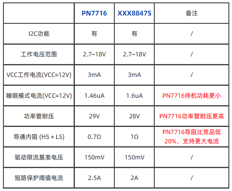
Summary:PN7716 has advantages over overseas competitor xxx8847S in terms of on-resistance and power transistor voltage resistance.
Free Sample Application

If you need to apply for samples, pleaselong press to identify the QR code or click to read the original text to fill in the information, and a professional will contact you!
Past Reviews


www.chipown.com
Providing you with efficient and reliable power semiconductor chips and solutions