The plug and terminal resistor play a very important role in Profibus communication. They are very simple to use and do not require many complex settings; however, due to their simplicity, many engineers overlook some details during use, leading to various communication issues.(1) Structure and Simple Usage of Profibus Plugs
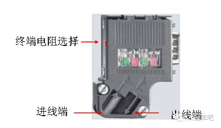 Figure 1: Structure of Profibus Plug
This is a common Profibus plug. If we have two stations A and B that need to communicate via Profibus, how should the plugs be connected? Since there are only two stations on the bus, clearly, the terminal resistors must be set to ON. So, should the wiring on the plugs come in and out?
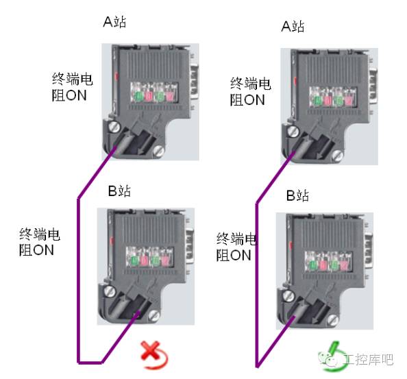 Figure 2: Connection of Two DP Stations
The correct approach is to connect both plugs to the incoming terminal: because the terminal resistor and the plug’s outgoing terminal are a choice of one, if the terminal resistor is set to ON, the incoming terminal connects to the terminal resistor, and disconnects from the outgoing terminal; if the terminal resistor is set to OFF, the incoming terminal disconnects from the terminal resistor and connects to the outgoing terminal.(2) Common Profibus Bus Connections
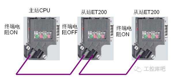 Figure 3: Master Station at One End of the Bus
As shown in Figure 3, this is a general method for connecting a Profibus bus, where the master station is located at one end of the bus, the terminal resistor is set to ON, and then the subsequent stations are connected sequentially, with the middle stations’ terminal resistors set to OFF, and the last station’s terminal resistor set to ON.
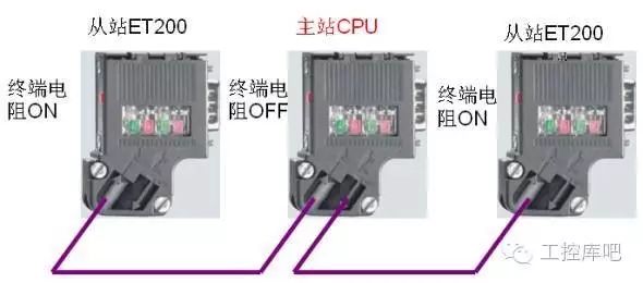 Figure 4: Master Station in the Middle of the Bus
Sometimes, due to the distribution of field devices, the master station can also be installed in the middle of the Profibus bus, as shown in Figure 4. The devices with terminal resistors set to ON cannot be powered off, as shown in Figure 5. In addition to the 220-ohm terminal resistor on the Profibus plug, there are also two 390-ohm bias resistors, and the bias resistors must be connected to power.
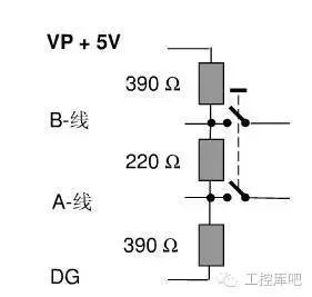 Figure 5: Terminal Resistor and Bias Resistor
If the terminal device needs to be powered off frequently for maintenance, or if the terminal device only has terminal blocks and no 9-pin D-type socket, an active terminal module should be used as the terminal of the Profibus bus (6ES7972-0DA00-0AA0).
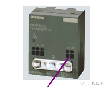 Figure 6: Profibus Active Terminal Module
If the Profibus cable is not long enough and two cables need to be connected, do not simply twist the two copper cores together, as this will damage the cable’s characteristic impedance and may lead to communication issues. It is best to use the connector shown in Figure 7 to connect the two cables that need to be joined.
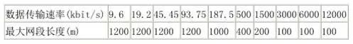
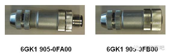 Figure 7: Profibus Connection Connector(3) Usage of Terminal Resistors on RS485 Repeaters The maximum length of the Profibus communication cable depends on the communication baud rate. If the cable exceeds the maximum communication length, an RS485 repeater is needed to extend the communication distance. Table 1 shows the relationship between bus length and transmission rate:
The repeater has terminal blocks, and the Profibus cable can be directly connected to the terminals. Additionally, the repeater is equipped with terminal resistors, and their usage is the same as that of the cable plug.
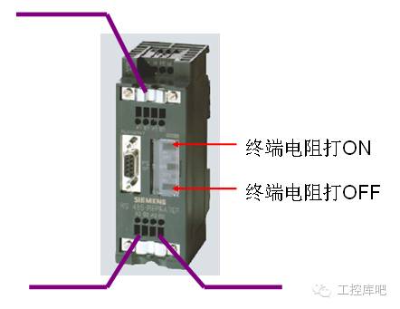 Figure 8: Segment 1 Only Has Incoming Line, Segment 2 Has Incoming and Outgoing Lines
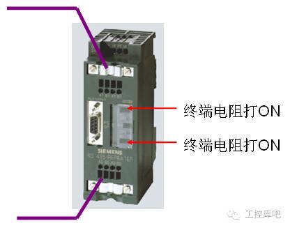 Figure 9: Segment 1 Only Has Incoming Line, Segment 2 Only Has Incoming Line
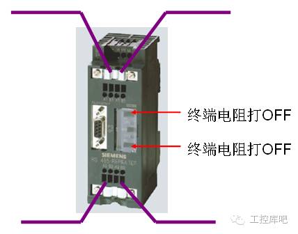 Figure 10: Segment 1 Has Incoming and Outgoing Lines, Segment 2 Has Incoming and Outgoing Lines
(4) Usage of Terminal Resistors on OLM Plugs
If the communication distance of field devices is relatively long, or if there is significant electromagnetic interference in the field, OLM can be used to convert electrical signals into optical signals, using optical cables for signal transmission. The OLM has RS485 electrical interfaces and requires Profibus plugs to connect the cables. Moreover, the electrical connection method for the OLM is the same whether connecting to a master or a slave station.
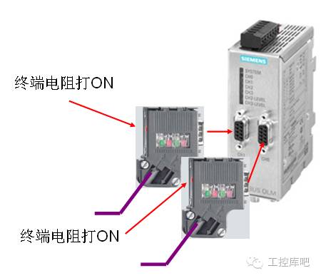 Figure 11: Segment 1 Only Has Incoming Line, Segment 2 Only Has Incoming Line
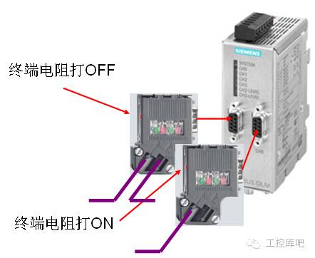 Figure 12: Segment 1 Has Incoming and Outgoing Lines, Segment 2 Only Has Incoming Line
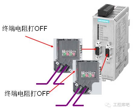 Figure 13: Segment 1 Has Incoming and Outgoing Lines, Segment 2 Has Incoming and Outgoing Lines
For an OLM with only one RS485 interface, it can be considered as having only segment 1, and the connection method is the same.(5) Usage of Terminal Resistors on DP/DP Couplers Two DP master stations can use a DP/DP coupler to transmit data. The DP/DP coupler has two RS485 interfaces, and the connection method is the same as that of OLM.
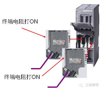 Figure 14: Segment 1 Only Has Incoming Line, Segment 2 Only Has Incoming Line
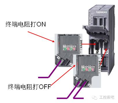 Figure 15: Segment 1 Only Has Incoming Line, Segment 2 Has Incoming and Outgoing Lines
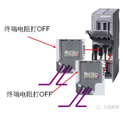 Figure 16: Segment 1 Has Incoming and Outgoing Lines, Segment 2 Has Incoming and Outgoing Lines
 For detailed usage of RS485, see:Detailed Explanation of Siemens RS485 Repeaters
For RS485 diagnostic methods, see:Siemens Repeater Diagnostic Methods
For Profibus fault diagnostics, see:Practical Methods for Diagnosing Profibus DP Communication Faults in S7-300/400 Systems
For more industrial control technology articles and videos, scan the QR code below