
Free FANUC/Yaskawa Industrial Robot Materials, Interested?
(Click on the red text above to receive the materials for free)
PROFIBUS is an open digital communication system with a wide range of applications, representing a significant breakthrough in the transition from centralized automation systems to decentralized automation systems.
Since its inception, PROFIBUS has focused on system integration and engineering, particularly in the research and development of application protocols, making it suitable for fast, time-critical applications and complex communication tasks. It has become the only fieldbus capable of comprehensively covering both factory automation and process automation applications, especially in these fields. Thus, PROFIBUS has remained a leader in the field of fieldbus technology in the international market.
With the extensive application of PROFIBUS, many users have started to engage with and utilize fieldbus technology. However, due to varying levels of understanding of fieldbus technology among users, combined with the complexity of on-site construction, there may be hidden dangers in many projects’ fieldbus communication. If not detected and addressed promptly, this could lead to communication failures in the system, affecting the normal operation of the entire system.
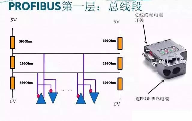
The essence of PROFIBUS network communication is RS485 serial communication. Depending on different industry applications, there are mainly three communication protocols: DP (Decentralized Peripherals), FMS (Field Message Specification), and PA (Process Automation).
1. Popularizing the Correct Wiring of PROFIBUS-DP
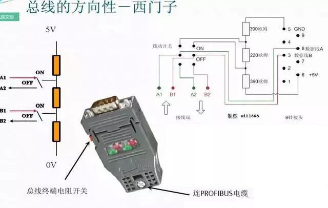
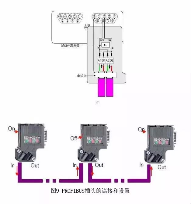
The correct wiring is shown in the figure below; it is self-explanatory. The PROFIBUS cable is very simple, consisting of only two wires inside: one red and one green, with a shielding layer outside. When wiring, ensure the shielding layer is properly connected and does not touch the internal wires. It is essential to distinguish between the incoming and outgoing wires. If it is a daisy chain, it means one main bus runs down with several sub-stations connected in between, which is a common method. At both ends of the bus, the wires must be connected to the incoming holes, not the outgoing ones. These two ends’ connectors should have their switches set to ON, meaning only the incoming connection is active while the outgoing connection is inactive. All other intermediate connectors should be set to OFF, allowing both incoming and outgoing connections (memory tip: ON indicates connecting terminal resistance, so the end connectors are set to ON; OFF indicates disconnecting terminal resistance, so the intermediate connectors must be set to OFF).
2. A Step-by-Step Guide on How to Connect and Purchase
Whether forming an MPI or PROFIBUS-DP network, the main components used are the same:
For specific cable and connector order numbers, please refer to: Common Accessories Order Numbers
A. Cables and Strippers. Using FC technology does not require stripping the exposed copper wire.

Figure 1. PROFIBUS cable stripped at one end with a quick stripper (FCS, order number 6GK1905-6AA00).
B. Opening the PROFIBUS Network Connector. First, release the cable tension clamp, then lift the core wire lock.
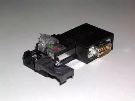
Figure 2. Opened PROFIBUS Connector
C. Remove the protective layer from the PROFIBUS cable core wire, insert the core wire according to the corresponding color markings into the core wire lock, and then press the lock block down firmly to ensure contact with the internal conductors. Note that the stripped shielding layer of the cable must be in contact with the shielding connection clamp.
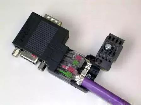
Figure 3. Inserting the Cable
Because of the high communication frequency, the communication cable is grounded at both ends. The shielding layer must be connected at both ends of the cable.
D. Reset the cable clamp, tighten the screws, and eliminate external tension affecting the internal connection.
The network connectors are mainly divided into two types: with and without programming ports. The connectors without programming ports are used for general networking, while those with programming ports can still provide a programming connection while being networked, suitable for programming or connecting HMI, etc.
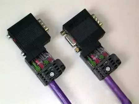
Figure 4. Left: Network connector without programming port (order number: 6ES7 972-0BA52-0XA0); Right: with programming port
By connecting the PROFIBUS cable to the network plug, a bus-type network structure is formed.
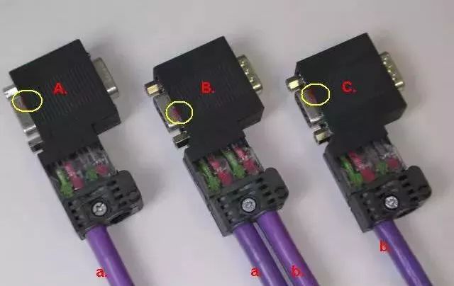
Figure 5. Bus-type Network Connection
In the above figure, network connectors A, B, and C are inserted into the communication ports of three communication stations; cable a connects plug A and B, while cable b connects plug B and C. The linear structure can be extended accordingly.
Note the settings of the “terminal resistance” switch within the circles. The terminal resistance switch of the network terminal plug must be set to the “ON” position; the terminal resistance switch of the intermediate station plugs should be set to the “OFF” position.
Editor Recommends
Unveiling the Secrets of the Industrial Control Community!
Let the editor take you to learn the little secrets of the industrial control community!
Get Free: ABB Industrial Robot Materials!
Limited Time Offer: Do You Want This Excellent KUKA Industrial Robot Material?
With Zero Foundation, How Can You Become an Excellent Electrical Engineer?
▣ Source:Headline Account/Industrial Control Automation Alliance, Copyright belongs to the original author, if there is any infringement, please contact for deletion, thank you!
▣ Disclaimer: The material in this article is collected from the internet, edited and organized by the Industrial Control Cloud Academy. The videos, images, and text used in this article are copyrighted by the original authors. However, due to the numerous reprints, it is impossible to confirm the true original authors, hence only the source of reprint is indicated. If there are copyright issues with the works, please contact 18817120051 (WeChat same number), and we will immediately confirm the copyright and pay remuneration according to national regulations!

▣ Suggestion: The article may inevitably contain omissions or errors. Please feel free to express your opinions in the comment area; what you know may be exactly what everyone wants to understand! This way, we can help more people learn more! Thank you for your support!