
1. Basic Properties of PROFIBUS
PROFIBUS specifies the technical and functional characteristics of the serial fieldbus system. Through this system, distributed, digital field programmable controllers can be networked from the lower level (sensor, actuator level) to the middle level (unit level). PROFIBUS is divided into master and slave stations.
> Master Station The master station controls the flow of data on the bus. As long as it has bus access rights (token), the master can send information without external requests. In the PROFIBUS protocol, the master station is also known as the active node.
> Slave Station The slave station is a simple input/output device. Typical slaves include sensors, actuators, and frequency converters. Slaves can also be intelligent slaves, such as S7300/400 with integrated CPU interfaces. Slaves do not have bus access authorization. They can only confirm received information or send information at the request of the master station. Slaves are also known as passive nodes.
> Transmission Method The closed circuit transmission complies with the American standard EIA RS485, which is the basic standard for manufacturing engineering, building service management systems, and power engineering. It uses twisted pair copper conductors but can also use fiber optics.
> Transmission Speed The transmission rate of the PROFIBUS bus ranges from 9.6 Kbit/s to 12 Mbit/s.
Relationship Between Bus Length and Transmission Speed
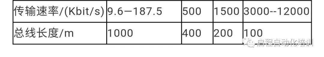 > Maximum Node Count 127 (addresses 0-126)
2. Types of PROFIBUS Field Applications
PROFIBUS provides three types of communication protocols: FMS, DP, and PA.
> PROFIBUS-FMS: Used for general communication tasks in the field with the FMS interface (DIN 19245 T.2).
> PROFIBUS-DP: Used for high-speed communication with distributed I/O.
> PROFIBUS-PA: Used for devices that execute specified field device characteristics, utilizing an extended PROFIBUS-DP protocol for data transmission.
3. Communication Using PROFIBUS DP
PROFIBUS-DP is designed for fast data exchange at the sensor-actuator level. The central control unit (e.g., programmable controller) communicates with distributed input and output devices through a fast serial interface. Communication with these devices generally occurs cyclically.
The central controller (master station) reads input information from the slave and writes output information to the slave.
A single master or multiple master systems can be implemented through PROFIBUS-DP. This makes system configuration exceptionally convenient. A single bus can connect up to 126 devices (master or slave).
> System Configuration
The specifications for system configuration include a series of sites, allocation of I/O addresses, integrity of input/output data, formatting of diagnostic information, and bus parameters.
> Device Types
DP1 Class Master Station This is a central controller that exchanges information with distributed sites (DP slaves) within a given information cycle.
Typical devices include: Programmable Controllers (PLC), Computer Numerical Control (CNC), or Computers (PC).
DP2 Class Master Station Devices in this category include programmers, configuration devices, and diagnostic devices, such as upper-level machines. These devices are used to generate the system configuration during DP system initialization.
DP Slave Station A DP slave station is an input/output device (sensor/actuator) that reads and writes process information, such as distributed I/O, ET200, frequency converters, etc.
Implementing Master-Slave Communication Between Two CPUs Using PROFIBUS-DP
PROFIBUS-DP slaves are not just remote I/O stations of the ET200 series; they can also be intelligent slaves, such as S7 300 stations with integrated DP interfaces and PROFIBUS communication modules, S7400 stations (V3.0 and above) can also serve as DP slaves. Below we will introduce the configuration method for connecting intelligent slaves using an example of master-slave communication between two CPU315-2DP CPUs.
1. Hardware and Software Requirements
Hardware:
PROFIBUS-DP Master Station S7-300 CPU315-2DP (6ES7 315-2AG10-0AB0), SM374
PROFIBUS-DP Slave Station S7-300 CPU315-2DP (6ES7 315-2AG10-0AB0); SM374
PROFIBUS cable and connectors
CP5512 (PCMCIA card for laptops) or PC adapter, CP5611 (PC)
Software:
STEP7 V5.3 SP2
2. Network Configuration and Parameter Settings
1) Create a New Project:
In STEP7, create a new project, then select Insert ® Station ® Simatic 300 station, insert two S7 300 stations, naming them Simatic 300 (master) and Simatic 300 (slave). Alternatively, you can complete the configuration of one station before creating another. As shown in Figure 1.
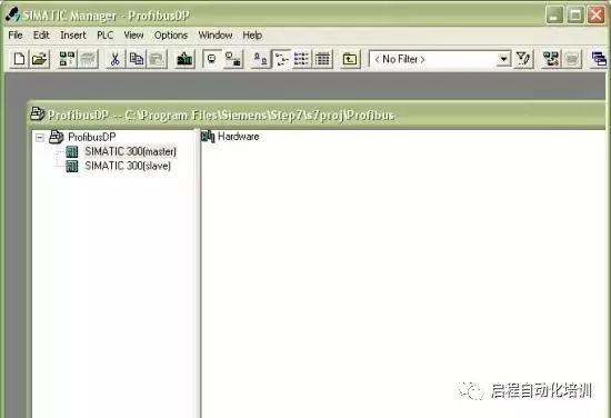
Figure 1 Inserting Two S7 300 Stations in STEP7 Hardware Configuration
2) Configure the Slave: In the configuration of the two CPU master-slave communication, the principle is to configure the slave first.
> Hardware Configuration
Double-click on Simatic 300 (slave) “Hardware” to enter the hardware configuration window. Click the “Catalog” icon in the function button bar to open the hardware catalog, and insert the rack, power supply, CPU, and SM374 in order to configure the hardware.
When inserting the CPU, the PROFIBUS interface configuration window will pop up. You can also insert the CPU first, double-click on the DP (X2) slot, and open the DP properties window to access the PROFIBUS interface configuration window. Click the “NEW” button to create a new PROFIBUS network, assigning the PROFIBUS station address, which is set to station 3 in this example. Click the “Properties” button to configure network properties, selecting “Network Setting” for network parameter settings, such as baud rate and line protocol. In this example, the transmission rate is set to 1.5 Mbit/s, and the line protocol is DP. As shown in Figure 2.
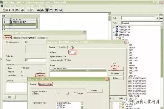
Figure 2 PROFIBUS DP Network Parameter Settings
After confirming the above settings, the PROFIBUS interface status is shown in Figure 3.
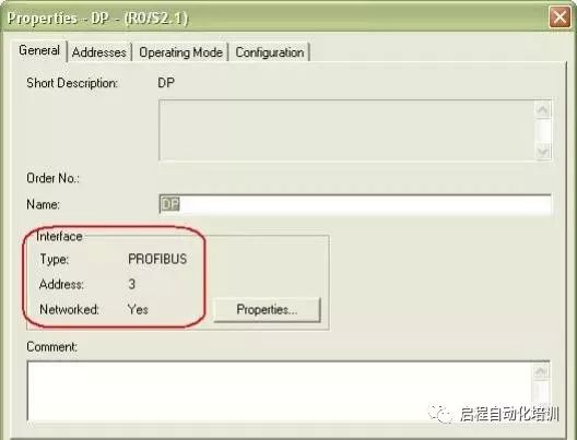
Figure 3 PROFIBUS Interface Status
> DP Mode Selection
In the DP properties setting dialog, select the “Operating Mode” tab and activate the “DP slave” operating mode. If the “Test, commissioning, routing” option is activated, it means this interface can act as both a DP slave and monitor the program through this interface. Detailed information can also be viewed using the STEP7 F1 help function.
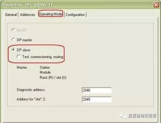
Figure 4 DP Mode Selection
> Define Slave Communication Interface Area
Select the “Configuration” tab to open the I/O communication interface area property settings window, then click the “New” button to create a new communication interface area. As shown in Figure 5, the current configuration mode is master-slave (MS, Master-slave configuration). Note that at this point, only the local (slave) communication data area can be configured.
Address type: Choose “Input” for the input area and “Output” for the output area.
Address: Set the starting address of the communication data area.
Length: Set the size of the communication area, up to 32 bytes.
Unit: Choose whether to communicate by byte or by word.
Consistency: Choose “Unit” to send according to the data format defined in “Unit”, i.e., by byte or by word;
If “All” is selected, it means sending in packets, with a maximum of 32 bytes per packet. If the communication data exceeds 4 bytes, SFC14 and SFC15 should be applied.
After completing the setup, click the “Apply” button to confirm. Similarly, several rows can be created based on the actual communication data, but the maximum cannot exceed 244 bytes. In this example, an input area and an output area are created, each with a length of 4 bytes, and after setup, these two communication interface areas can be seen in the “Configuration” window, as shown in Figure 6.
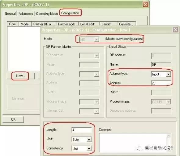
Figure 5 Communication Interface Area Settings
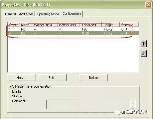
Figure 6 Slave Communication Area After Setup
> After Completing the Communication Area Setup, Click the Compile and Save Button. Once Compiled Without Errors, the Slave Configuration is Complete.
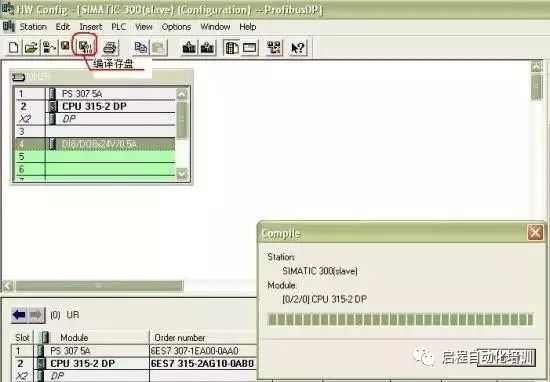
Figure 7 Slave Compilation and Saving
3) Configure the Master Station
> After Completing the Slave Configuration, You Can Configure the Master Station, The Basic Process is Similar to That of the Slave. After Completing the Basic Hardware Configuration, Set the DP Interface Parameters, as Shown in Figure 8. In this example, the address is set to 2, and the same PROFIBUS network (PROFIBUS1) is selected as the slave. The baud rate and line protocol should also be set the same as the slave. (1.5 Mbit/s; DP).
> Then in the DP properties setting dialog, select the “Operating Mode” tab and choose “DP Master” operating mode. As shown in Figure 9.
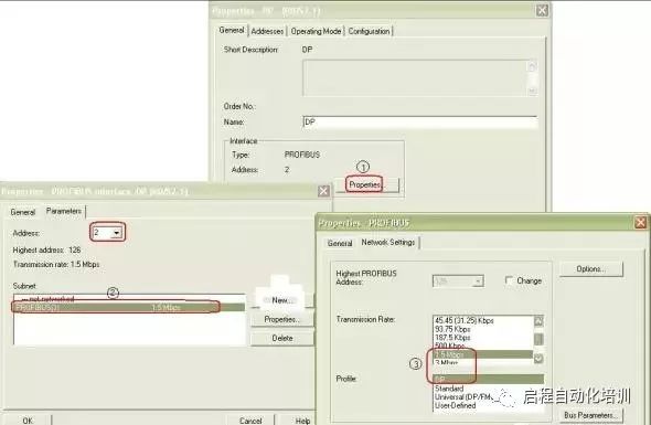
Figure 8 Master Station DP Interface Parameter Settings
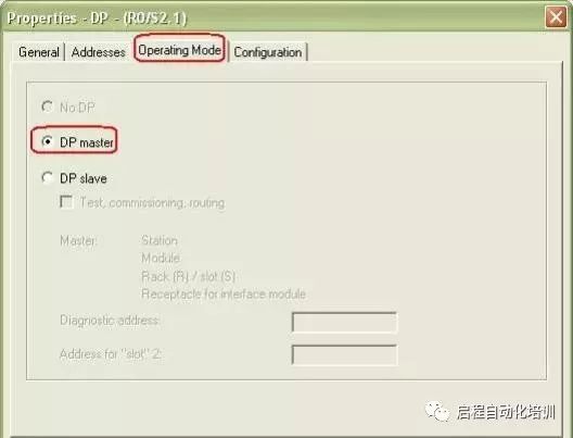
Figure 9 DP Interface as Master Station
> Connecting the Slave: In the hardware configuration (HW Config) window, open the hardware catalog, select the “PROFIBUS DP ® Configured Stations” folder, and drag the CPU31x to the master station system DP interface on the PROFIBUS bus. A DP slave connection properties dialog will pop up, select the slave to connect, and click the “Connect” button to confirm. As shown in Figure 10.
Note: If multiple slaves exist, they must be connected one by one.
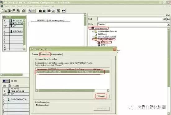
Figure 10 Connecting the Slave
> Communication Interface Area: After the connection is complete, click the “Configuration” tab to set the master station’s communication interface area corresponding to the slave’s output area and the master station’s input area corresponding to the slave’s input area, as shown in Figure 11. Figure 12 shows the completed I/O communication area settings.

Figure 11 Communication Data Area Settings

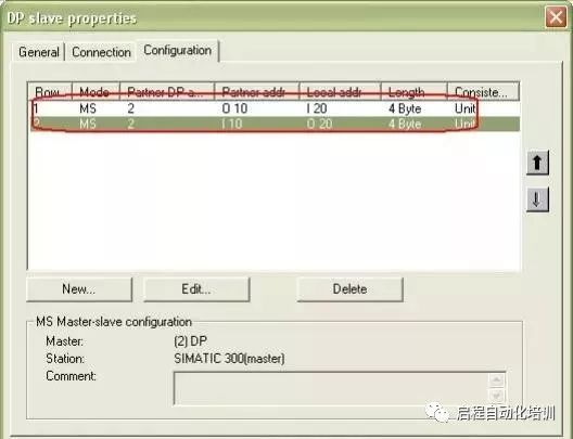
Figure 12 Communication Data Area
After confirming the above settings, in the hardware configuration (HW Config), select the compile and save button, and once compiled without errors, the master-slave communication configuration is complete.
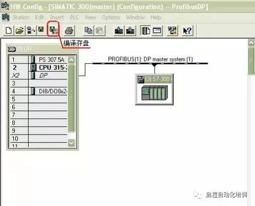
Figure 13 Compilation and Saving of Configuration
Simple Programming: During the program debugging phase, it is recommended to download OB82, OB86, and OB122 to the CPU, so that the CPU can still operate when the above interrupts are triggered. Related OB explanations can be referenced in the STEP7 help.
Reprinting is a kind of power. Sharing is a virtue.
About Us: Qicheng Automation Training, China’s leading industrial robot training service provider.
Contact Number:0755-33160627 13809869603
Training Projects:Robot + PLC System Integration + Motion Control + Robot + Machine Vision
Special Services:3000 square meters of training center + recommended employment + industry-leading curriculum system.

+ Teacher WeChat, learn about class opening details