In Siemens automation systems, the use of the Profibus DP bus is very common. It is essential to diagnose and detect faults in the bus devices during operation. Today, I will summarize these issues briefly, hoping that after learning, everyone can complete the diagnostics and monitoring of the DP bus.
When applying PROFIBUS-DP and SIMATIC S7 for diagnostic evaluation of remote configuration, user programs can utilize two different S7 function blocks.
If detailed information about errors and faults on the bus nodes is needed in addition to the diagnostic summary, please use function block FB125.
Function block FC125 is a simplified version that only provides information about which bus nodes have faults or errors (diagnostic summary). This function block cannot display detailed information.

FB125 and FC125 can be used for the following integrated DP interfaces and external DP interfaces:CPU 313C-2 DPCPU 314C-2 DPCPU 315-2 DP (from 6ES7 315-2AF02-0AB0)CPU 315-2 DP (only for 6ES7 315-2AF01-0AB0):FC125 cannot be usedFB125 cannot detect faulty slaves through Start/RESETCPU 316-2 DPCPU 318-2 DPC7-626 DP (from 6ES7 626-2AG01-0AE3)C7-633 DP and C7-634 DPSINUMERIK 840D with integrated CPU315-2 DP (6ES7 315-2AF01-0AB0):FC125 cannot be usedFB125 cannot detect faulty slaves through Start/RESETSINUMERIK 840DI, with integrated CPU315-2 DP (6ES7 315-2AF03-0AB0)CPU 41x-2/3/4 DPCP 443-5IM 467 and IM 467 FOWIN ACWIN LCNot applicable for CP 342-5

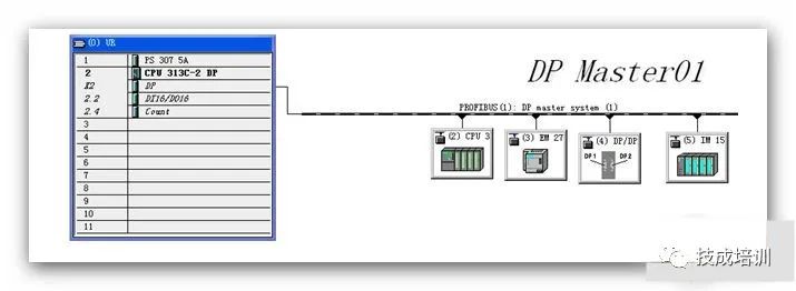
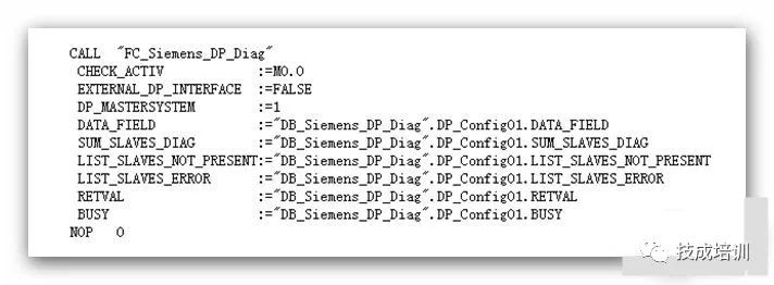
This section introduces how to call FC125 [FC_Siemens_DP_Diag] to complete the diagnostics of the Profibus bus using the following hardware configuration.

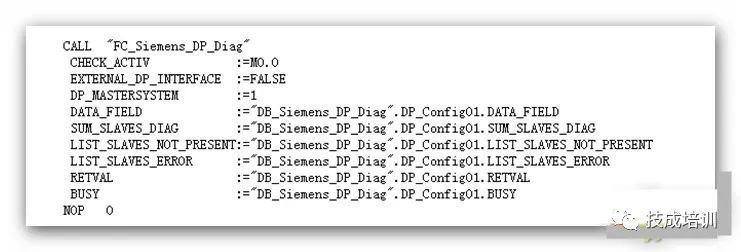
Interface Parameter Description
CHECK_ACTIVE :When 1, start detecting slaves.EXTERNAL_DP_INTERFACE :Select the DP master station interface, 0 indicates the integrated DP master station on the CPU, 1 indicates an external DP master station interface, such as CP443-5.DP_MASTERSYSTEM :PROFIBUS ID number, which can be viewed in hardware configuration. If there are multiple PROFIBUS networks, FC125 needs to be called multiple times, assigning their PROFIBUS ID numbers, data type is INT.DATA_FIELD :A 50-byte data area for internal use by FC125, data type is POINTER.SUM_SLAVES_DIAG :Total number of slave diagnostics, data type is INT.LIST_SLAVES_NOT_PRESENT:Checks for missing slaves (software configured but hardware not connected), a 16-byte data area, each bit corresponds to a slave, setting 1 indicates a slave is missing, if the missing slave returns or is repaired, the corresponding bit resets. Data type is POINTER.LIST_SLAVES_ERROR :Faulty slaves (some modules have faults, others can continue to operate), a 16-byte data area, each bit corresponds to a slave, setting 1 indicates a slave is faulty, if the faulty slave returns or is repaired, the corresponding bit resets. Data type is POINTER.RETVAL :Status return value when calling FC125, data type is INT.BUSY :When 1, indicates currently executing.


[Note: When CHECK_ACTIVE, m0.0=1, the diagnostic function is enabled]

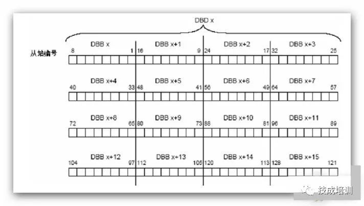
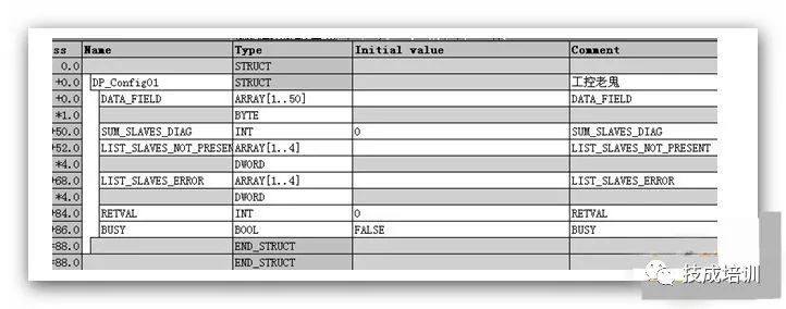
After processing the above program, two data areas LIST_SLAVES_NOT_PRESENT and LIST_SLAVES_ERROR can be obtained. Each of these parameters has 16 bytes of data. Each bit of these 16 bytes represents a DP slave device. It can represent 16×8=128 stations.
If a bit is set to 1, it indicates that the slave represented by that bit is missing or faulty; however, if the fault disappears, that bit will automatically reset to 0. For DP network 1, it has 4 slaves, and their diagnostic bits
are in “GLOBAL_DIAG_DB”.DP_SLAVE1.LIST_SLAVES_NOT_PRESENT or “GLOBAL_DIAG_DB”.DP_SLAVE1.LIST_SLAVES_ERROR data area bits 1-4, while for DP network 2, which has 3 slaves, the bits are in “GLOBAL_DIAG_DB”.DP_SLAVE2.LIST_SLAVES_NOT_PRESENT or “GLOBAL_DIAG_DB”.DP_SLAVE2.LIST_SLAVES_ERROR data area bits 1-3.
The next question is, how to extract the diagnostic bit information corresponding to the slaves from the diagnostic dataset.There are many methods, the most direct method is to directly find the absolute address of these bits in the DB, such as for the second slave of DP network 1, its missing diagnostic bit’s absolute address is: DB100.DBX52.1, and the fault diagnostic bit’s absolute address is: DB100.DBX68.1.
This method is simple and direct but not conducive to program migration.The indirect method is to shift the diagnostic bits in the diagnostic dataset to the rightmost end of a double word, which is the lowest bit of the double word, and then perform an XOR-NOT operation with the constant DW#16#1, if the result=1, then the shifted diagnostic bit indicates that the corresponding slave is missing or faulty.The specific method used to obtain the exact information of the diagnostic bits depends on the habits of the specific programmers. The important thing is how to use the diagnostic bits to control the process once the diagnostic bit information of the slaves is obtained.
Source: Internet, deletion upon request.
Stay tuned for the next exciting article:
Interview questions for electricians with a salary of over 9000 in large state-owned enterprises, see if you can successfully get the job?