1 Characteristics of PROFIBUS-DP
PROFIBUS-DP uses physical layer, data link layer, and user interface for high-speed data transmission at the field level. The master station periodically reads input information from the slave stations and sends output information to the slaves. The bus cycle time must be shorter than the master program cycle time. In addition, PROFIBUS-DP also provides non-periodic communication required for intelligent field devices for configuration, diagnostics, alarm processing, and determining parameters of complex devices during operation.
Basic functions and characteristics of PROFIBUS-DP are as follows:
(1) High-speed communication over long distances
Supports transmission rates from 9.6Kbps to 12Mbps; at 12Mbps, the maximum transmission distance is 100m, and at 1.5Mbps, it is 200m; it can also be extended using repeaters;
(2) Distributed architecture
Token passing between master stations, master-slave transmission between masters and slaves; each segment can have 32 stations, expandable to 126 stations using connection cables;
(3) Easy installation, open communication network;
(4) High reliability with self-diagnostic capabilities.
PROFIBUS-DP master stations are divided into Class 1 and Class 2 masters. Class 1 masters complete bus communication control and management, performing periodic data access, including PLC, PC, or controllers that can act as Class 1 masters. Class 2 masters perform non-periodic data access, such as data read/write, system configuration, fault diagnosis, etc., including operator workstations (such as PCs with graphical monitoring software), programmers, HMIs, etc. PROFIBUS-DP slave stations primarily collect and send input and output signal data, including PLC or other controllers, distributed I/O, intelligent field devices, etc.
2 Wiring of PROFIBUS-DP
1. The PROFIBUS bus is a purple shielded twisted pair, with the two cores being red and green; when connecting to the bus connector, the wiring must follow the color scheme, generally A1, A2 are green, B1, B2 are red.
2. Devices on the PROFIBUS bus are connected in a series, so the two terminal devices are connected to the incoming end of the bus connector (A1 and B1), while the intermediate devices connect the incoming to A1, B1 and the outgoing to A2, B2.
3. The position of the terminal resistor switch is set to “ON” for the terminal devices (those that only have incoming connections) and “OFF” for the intermediate devices. This is because each bus connector has a 200-ohm terminal resistor, and only the terminal devices need to connect the terminal resistor to match the impedance on the bus and reduce signal attenuation. When the terminal resistor is in the ON position, A1, B1 are connected to the terminal resistor and disconnected from A2, B2; when the terminal resistor is in the OFF position, A1, B1 are disconnected from the terminal resistor and connected to A2, B2.
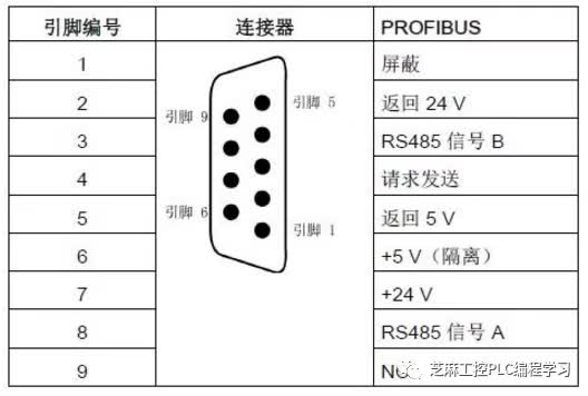
4. After wiring is completed, it is best to use a multimeter to check the connections. A1, B1 and the pins 3 and 8 of the bus connector should be connected, so you need to measure continuity between the pins 3 of both connectors and between the pins 8, and check if the resistance between 3 and 8 is around 110 ohms (since both ends are connected to the terminal resistor, equivalent to two 220-ohm resistors in parallel).