
For friends who are new to industrial automation, Siemens PLC may seem a bit complex. Don’t worry, today we will break it down step by step to see how to design a simple yet practical industrial control system using Siemens PLC.
Understanding the Basic Components of PLC

PLC mainly consists of the CPU, input/output modules, power supply module, and programming device. You can think of PLC as a small computer that receives signals from various sensors through the input module, makes judgments based on pre-written programs, and finally controls various actuators through the output module.
Selecting the Right PLC Model

For beginners, it is recommended to start with the Siemens S7-200 series. It has a simple structure and intuitive programming, making it very suitable for beginners. For example, the CPU 224XP is a good choice, with 14 digital input points and 10 digital output points, sufficient to handle most simple control tasks.
Hardware Connections

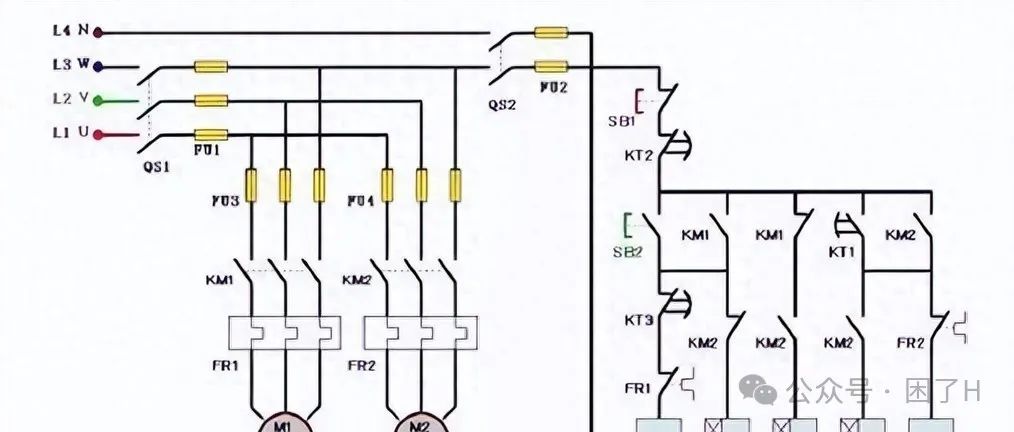
When connecting the PLC, pay special attention to the following points:
-
Wiring must be secure, loose connections may cause equipment malfunction.
-
The input devices (such as buttons and sensors) connect to the input terminals.
-
The output devices (such as indicator lights and solenoid valves) connect to the output terminals.
-
All devices share the 0V terminal.
Below is a simple wiring diagram:
                 +24V
                  |
       [Button]-----|---[I0.0]
                  |
       [Sensor]---|---[I0.1]
                  |    PLC
       [Indicator]---|---[Q0.0]
                  |
       [Valve]---|---[Q0.1]
                  |
                 0V
Writing the PLC Program

Siemens PLC mainly uses ladder diagram language for programming. You can imagine the ladder diagram as a series of circuits, with the left side being the input conditions and the right side being the output results.
Below is a simple start-stop control program:
|   Start     Stop     Run
|---| |------| |---+--( )---
|          |      |
|          |      |
|          +------+
The logic of this program is: after pressing the start button, even if the button is released, the device will continue to run, and it will only stop when the stop button is pressed.
Practical Application Case: Water Tank Level Control

Assuming we want to control the water level of a tank, we will need the following devices:
-
Low-level sensor (I0.0)
-
High-level sensor (I0.1)
-
Water inlet pump (Q0.0)
The control logic is as follows:
-
When the water level is below the low-level sensor, start the water inlet pump.
-
When the water level reaches the high-level sensor, turn off the water inlet pump.
The ladder diagram program is as follows:
|   Low Level   High Level   Inlet Pump
|---| |------| |---+--( )---
|          |      |
|          |      |
|   Inlet Pump  |      |
|---| |-----+------+
Notes:
-
Ensure the sensor installation position is correct to avoid misreading the water level.
-
Consider adding an alarm function, such as an alarm when the water level is too high or when the pump fails.
-
A manual control switch can be added for ease of maintenance.
Program Download and Debugging

-
Connect the PLC to the computer using a programming cable.
-
Open the Siemens programming software (such as STEP 7-Micro/WIN).
-
After writing the program, click “Download” to transfer the program to the PLC.
-
Switch to “Online” mode to observe the program running status.
-
If problems are found, you can modify the program in real-time and re-download.
Debugging Tips: You can use the PLC’s force function to simulate various input signals and test the program’s response under different conditions.
Common Issues and Solutions

-
Program cannot be downloaded
-
Check if the communication cable is correctly connected.
* Confirm that the communication parameters of the PLC and computer are consistent.
-
Output does not operate
-
Check if the output points are correctly wired.
* Confirm if the program logic is correct.
* Check if there are other conditions preventing the output.
-
Program runs unstably
-
Check if the power supply is stable.
* Investigate if there are interference sources (such as high-power motors).
* Consider adding filtering circuits.
Conclusion

Designing a PLC control system requires consideration of many factors. Not only must one master basic programming skills, but also understand the characteristics of field devices. It is recommended to start practicing with simple control tasks and gradually increase the difficulty. Read relevant technical materials and accumulate practical experience to design stable and reliable control systems.
Practical exercise suggestion: Find a small water pump and several float switches to build a real water tank level control system. This will not only deepen your understanding of PLC programming but also teach you many practical engineering details.
Click to read more and learn more.
