1. Overview
This article introduces the configuration of FANUC Robot Profibus communication as a slave, with a master station being a PLC that has Profibus DP functionality. The main steps are as follows:

2. Operation Steps
1. Confirm the Robot Profibus Functionality
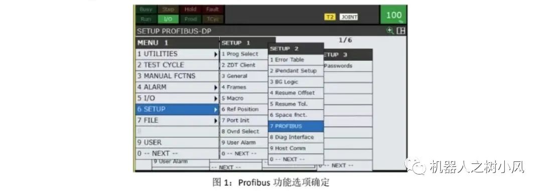
First, confirm whether the robot is equipped with the Profibus functionality. Select the [Menu] key on the teach pendant — look for the Profibus function in item 6 [Setup] menu as shown in Figure 1 below. If it is present, it indicates that the Profibus function is installed. If not, you need to contact FANUC personnel for installation.
2. Confirm Installation of the PLC Side GSD File
Import the GSD file provided by FANUC into the PLC programming software for installation, as required by the electrical PLC engineer. On the PLC side, you need to set the input and output byte sizes, baud rate, and station address.
3. Set SLAVE
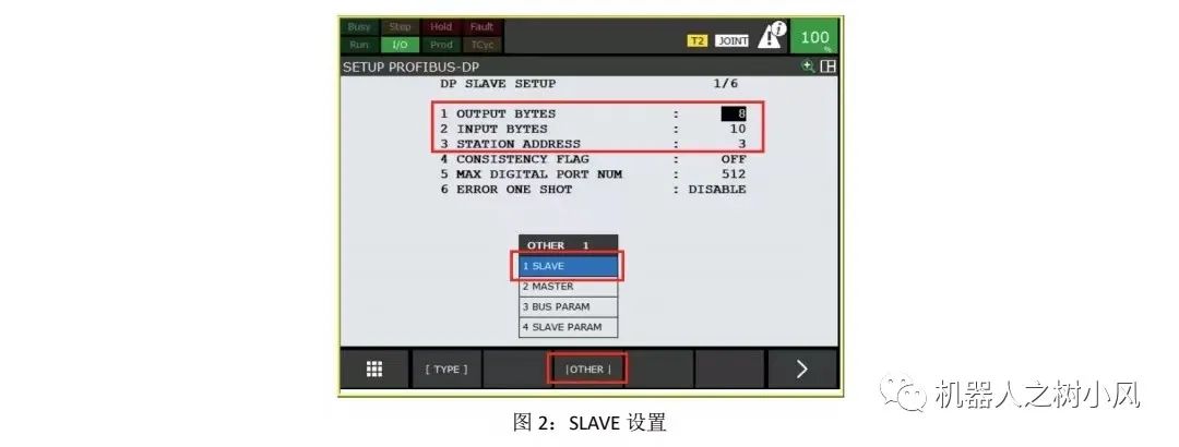
On the robot teach pendant, enter the main menu → 6 Setup → Profibus, then press F3 [OTHER], select 1 SLAVE, and enter the interface shown in Figure 2 below. According to the PLC requirements, set the first item OUTPUT BYTES, the second item INPUT BYTES, and the third item STATION ADDRESS.
4. Set BUS PARAM
Enter the main menu → 6 Setup → Profibus, press the F3 key to select BUS PARAM. The first item is to set the station address, and the second item sets the baud rate, which must match the master station settings. The other options do not need to be set, as shown in Figure 3 below.

5. Communication Test After Setup
After the electrical engineer completes the Profibus setup on the PLC side, conduct a communication test between the robot and the PLC.
On the robot teach pendant, select the [Menu] key — in the 5th item [IO] menu, select Digital, send a DO signal to the PLC, and check if the PLC receives the corresponding signal. If it does, it indicates that communication is OK and the signal test is normal. If communication is abnormal, check if there are any errors in the settings on both the PLC and robot sides.
3. Precautions
Common Alarms
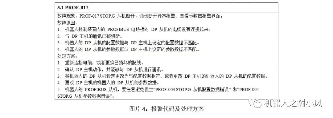
1. The possible alarms that may occur during the configuration process and their solutions are shown in Figure 4 below.
2. To suppress the PRIO-017 alarm, enable the 6th item ERROR ONE SHOT on the Profibus settings page. During normal production, this item must be set to disabled.