(1) Overview of PROFIBUS PA Bus
PROFIBUS is the abbreviation for “Process FieldBus”, which officially became the international standard for fieldbus in 1989. It currently dominates various automation fields and consists of three parts:
-
PROFIBUS DP
-
PROFIBUS PA
-
PROFIBUS FMS
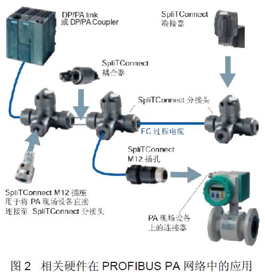
PROFIBUS PA is suitable for process automation design, applying intrinsically safe transmission technology (Manchester coding, bus power supply), transmitting digital data and power over a two-wire cable. It is best suited for directly integrating pneumatic actuators, solenoid valves, and sensors in hazardous environments (Ex Zone 1 or Ex Zone 0) into process control systems. The PROFIBUS PA network can be connected to the DP network using DP/PA connectors (DP/PA Link) or DP/PA couplers (DP/PA Coupler). The actual project should consider the following aspects when configuring related hardware devices:
-
Configuration Cost
-
Ex Zone
-
System Bus Communication Rate Requirements
-
Number of Instruments, Instrument Distribution, and Bus Structure
-
Whether the Automation System is Redundant
-
Whether the PROFIBUS PA Bus is Redundant
(2) Basic Configuration Rules for PROFIBUS PA Bus
For the characteristics of the two schemes of DP/PA couplers and DP/PA connectors, please refer to the table below:
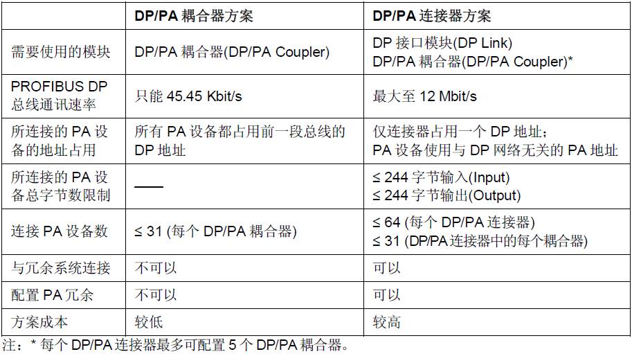
Table 1 Comparison of DP/PA Connector and DP/PA Coupler
 It is recommended to use the DP/PA connector scheme:
In this way, the transmission rate of the PROFIBUS DP network is independent of the PROFIBUS PA network, and PA devices will not occupy the DP addresses of the PROFIBUS DP network. Of course, in applications with a small amount of data communication (few instruments) and lower bus cycle time requirements, the DP/PA coupler scheme can also be a low-cost solution.
However, for S7-400H Redundant System:
PROFIBUS PA configuration can only use DP/PA connectors (redundant configuration): If you want to configure a redundant PROFIBUS PA bus, you must use DP/PA connectors. Additionally, multiple couplers (up to 5) can be configured on one DP/PA connector.
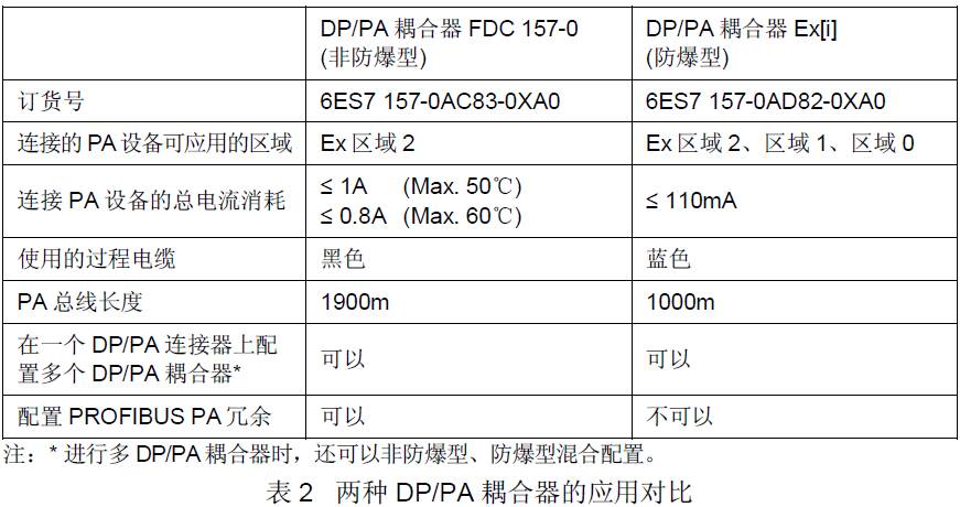
Couplers in the DP/PA coupler scheme or DP/PA connector scheme can use the two types of couplers in the table below. Their application comparisons can refer to the table below.
Additionally, when using the PROFIBUS PA network to connect instruments in the actual field, it is more related to the structure of the field PROFIBUS PA network and the degree of compliance with the specifications for connecting the PROFIBUS PA network.
The term “explosion-proof” refers to whether the connected PA instruments can be installed in explosion-proof areas (Ex Zone 1, Ex Zone 0), rather than referring to the couplers themselves. The above two types of couplers can only be installed in non-explosion-proof areas (Ex Zone 2).
(3) Various Solutions and Hardware Requirements for PROFIBUS PA Bus Configuration
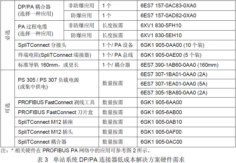
3.1 Single Station System DP/PA Coupler Low-Cost Solution
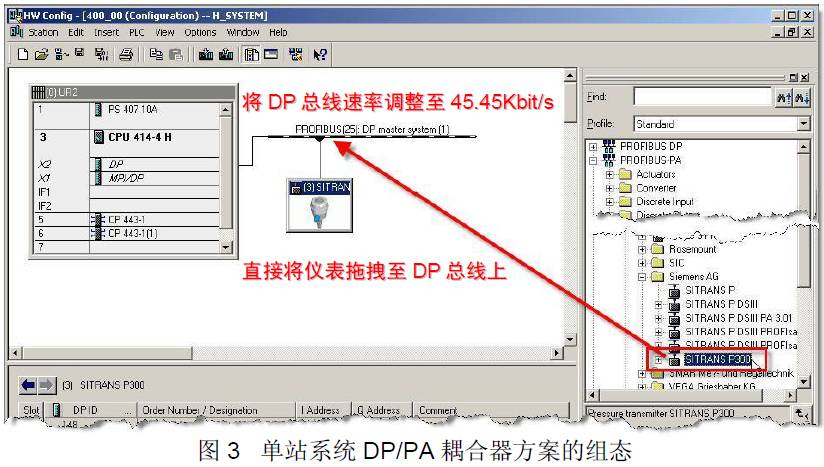
This solution is suitable for scenarios with small data communication volume, few instrument data, low bus cycle time requirements, and a need to save project costs. In this application, when configuring with STEP7, there is no need to consider the DP/PA coupler (the coupler has no address), and PA devices can be added directly to the PROFIBUS DP bus, but all PROFIBUS PA devices occupy the addresses of the PROFIBUS DP network. The hardware requirements for this solution can refer to the table below:
The hardware configuration process for this solution can refer to Figure 3.
3.2 Single Station System DP/PA Connector High-Speed Solution
This solution can be used in most scenarios and can meet the requirements of large data communication volume, many instrument data, and high bus cycle time requirements. In this application, when configuring the STEP7 network, it is necessary to configure the DP/PA connector.
The transmission rate of the PROFIBUS DP network can reach up to 12 Mbit/s: only the DP/PA connector will occupy one DP address in the PROFIBUS DP network, and all PROFIBUS PA devices connected behind the DP/PA connector are addressed independently of the PROFIBUS DP network before the DP/PA connector, referred to as PA addresses.
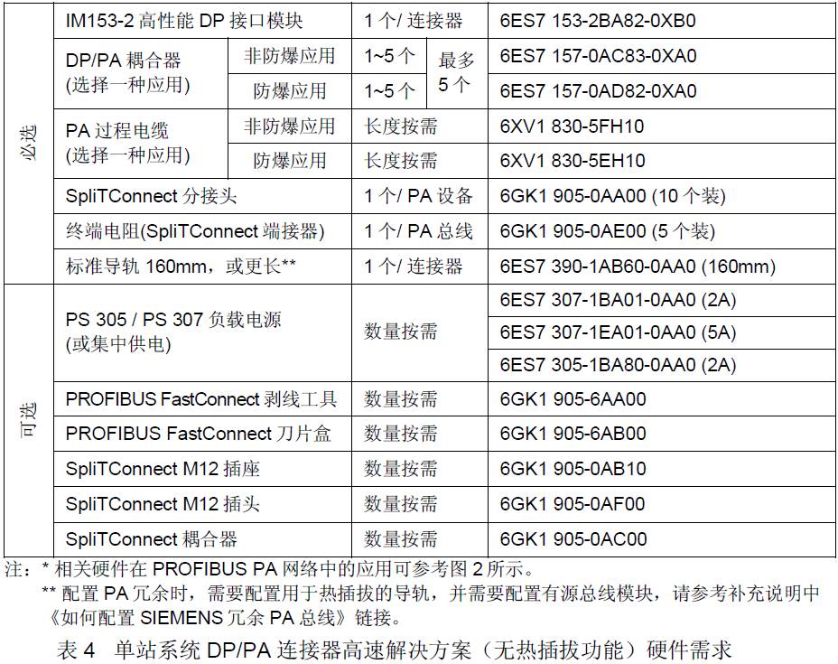
The hardware requirements for configurations without the “hot-swappable coupler” function can refer to the table below:
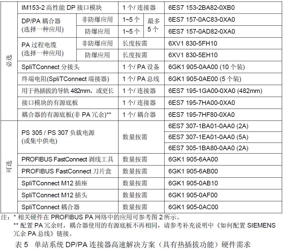
The hardware requirements for configurations with the “hot-swappable coupler” function can refer to the table below:
 The hardware configuration process for this solution can refer to Figure 4.
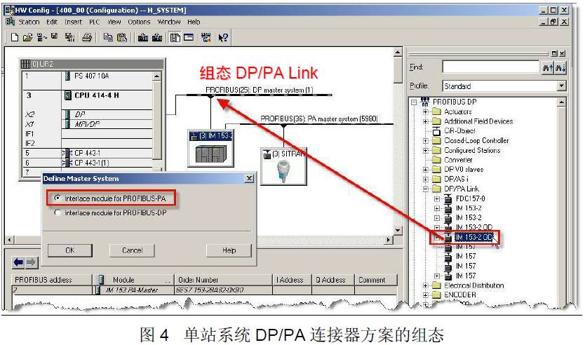
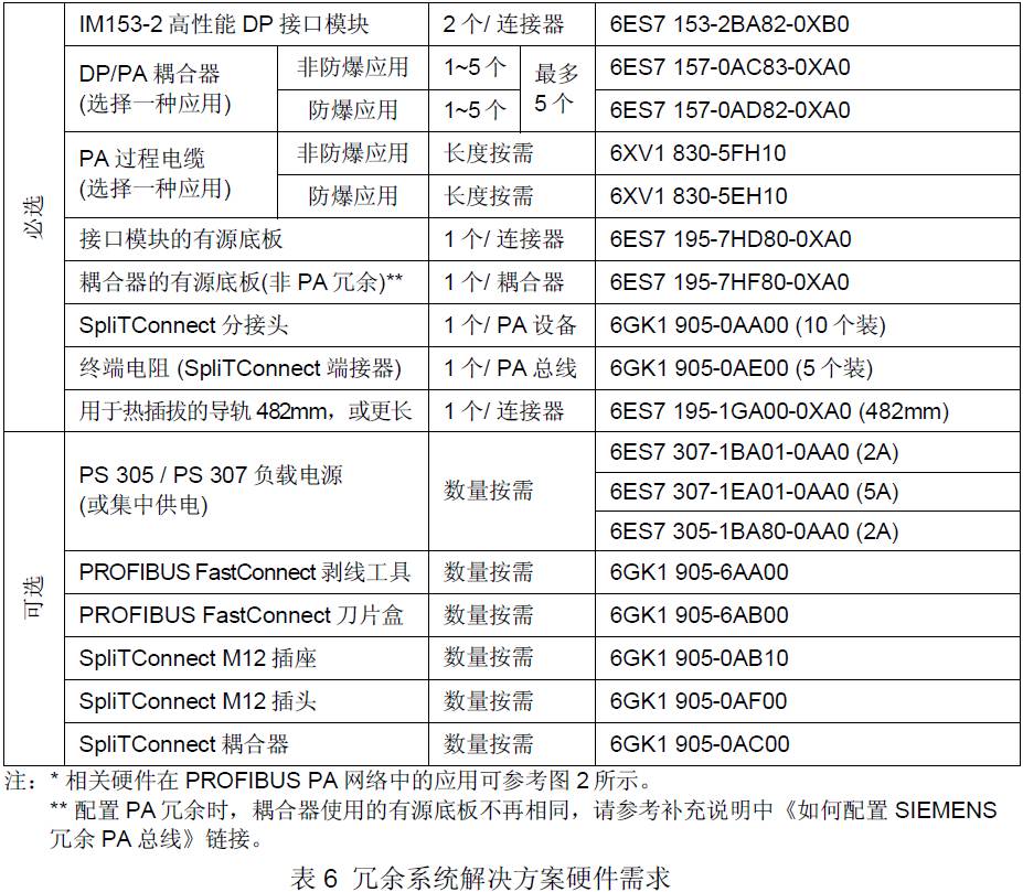
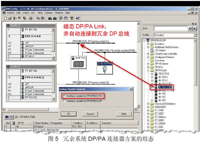
3.3 Redundant System Solution
This solution is used to extend the PROFIBUS PA network in a redundant system. In a redundant system, only DP/PA connectors with a redundant structure can be used, and an active backplane (i.e., bus module) must be used in this application. The characteristics of this solution can refer to the “Single Station System DP/PA Connector High-Speed Solution”. The hardware requirements for this solution can refer to the table below:
The hardware configuration process for this solution can refer to Figure 5.
(4) Supplementary Notes on PROFIBUS PA Bus Configuration
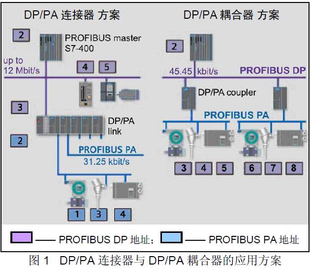
When using the DP/PA connector scheme, multiple couplers can be configured, with each DP/PA connector able to configure up to 5 couplers to extend the PROFIBUS PA network, as shown in Figure 1.
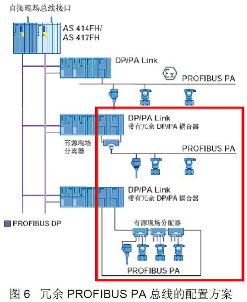
Siemens also provides configuration solutions for redundant PROFIBUS PA buses, where the two DP/PA couplers at the end of the DP/PA connector can be used to configure redundant PROFIBUS PA buses, as shown in Figure 6. Only non-explosion-proof couplers (DP/PA coupler FDC157-0) can be used to configure redundant PROFIBUS PA buses.
Stay Tuned for Next Issue’s Technical Solution for Configuring Redundant PROFIBUS PA
For more industrial control technology articles and videos, scan the QR code below