Introduction
Previous posts on controlling the servo and lead screw are as follows:
“Arduino Controls Stepper Motor to Move Lead Screw for Horizontal Movement of Servo Frame”
“Arduino Drives ST90S Micro Servo with Servo to Complete Cargo Picking Task”
Task Analysis
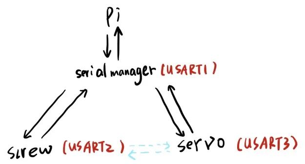
The allocation of UART data flow is roughly as shown in the image above. The black arrows indicate the UART data flow, which is quite understandable. The only part that is a bit difficult to understand is the blue arrows.
The blue arrows indicate that the servo driver board and the lead screw driver board communicate indirectly through the STM32F103 chip.
The STM32F103 plays a crucial role in parsing commands issued by the Raspberry Pi, accurately assigning tasks to the servo driver board and the lead screw driver board, and also parsing commands sent from the lead screw driver board and servo driver board to ensure communication between the two driver boards. This is essential for ensuring the stability of the entire UART data flow.
STM32CubeMX Configuration Project
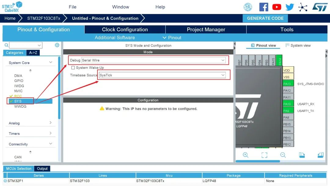
First, we configure SYS to Serial Wire and set the reference clock to SysTick.
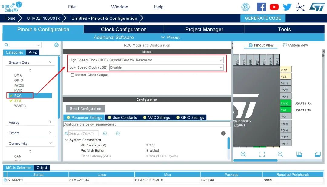
Next, configure RCC.
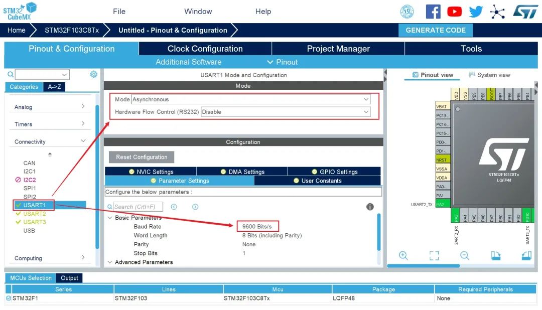
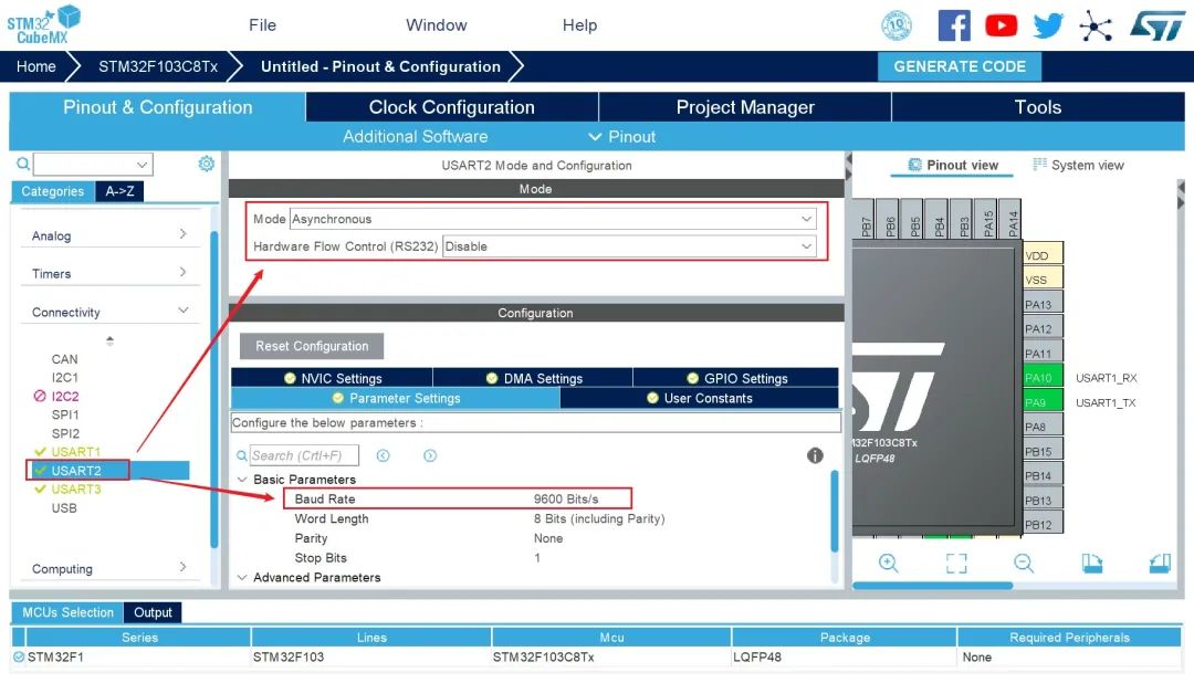
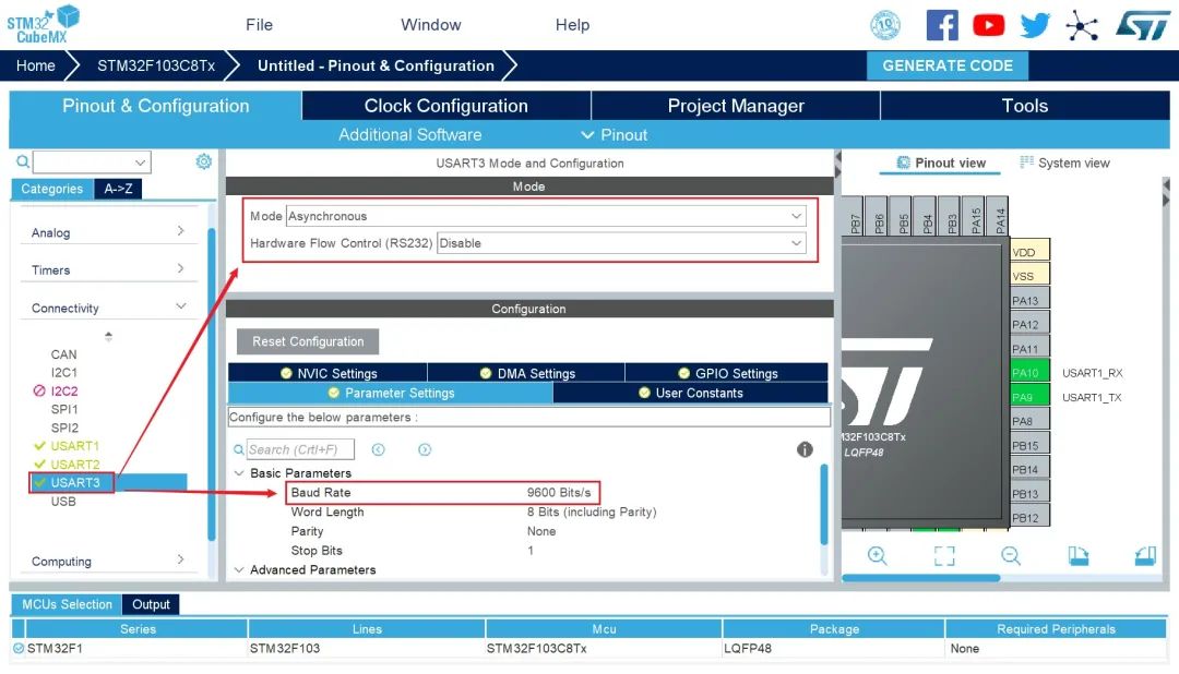
After completing the basic chip configuration, we start configuring the UART. Since the baud rate for both the servo driver board and the lead screw driver board is 9600, I configured the baud rates for USART2 and USART3 to 9600 as well. To maintain consistency, I also set the baud rate for communication between the STM32F103 and the Raspberry Pi to 9600, as shown in the configuration below.
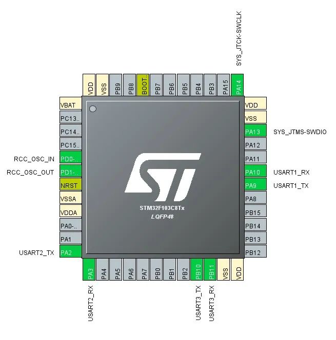
After completing the UART configuration, we can see the pin usage diagram of the chip as shown below.
At this point, we have completed the chip configuration. Next, we need to generate the project. I am using the development environment Keil5, so I selected the IDE MDK-ARM V5.
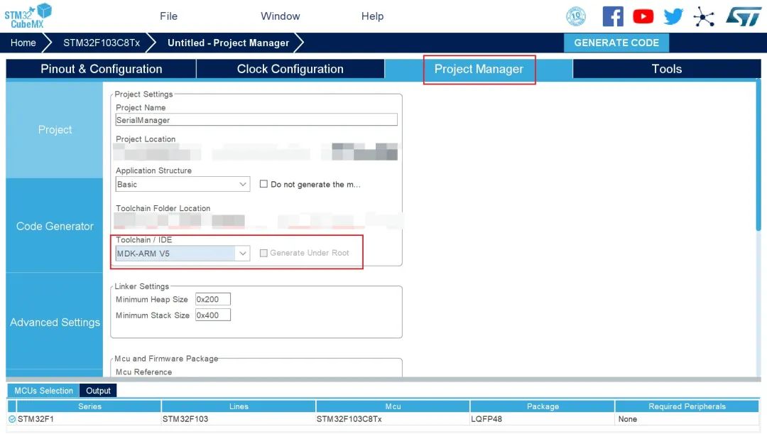
The two options in the image below are not checked by default, but to reduce the size of the generated Keil5 project files, I recommend checking both. The first is to include only necessary libraries, and the second is to categorize peripheral files by .c and .h.
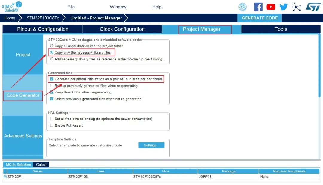
After completing the project configuration, click the file shown in the image below to generate the project.

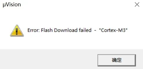
Then you can compile the generated project files. If you encounter the error shown in the image below, please refer to the article “CubeMX Configuration for STM32F103C8T6 Chip Debugging Photoelectric Sensors” (*https://www.guyuehome.com/29307)
Logic Writing
#define PI_SERIAL huart1#define SCREW_SERIAL huart2#define SERVO_SERIAL huart3Next, we will perform operations in the main loop of the program.
char pi_serial[7] = {'\0'};char servo_serial[4] = {'\0'};char screw_serial[3] = {'\0'};while (1){ if(!HAL_UART_Receive(&PI_SERIAL,(uint8_t *)pi_serial,6,0XFFFF)){//Received message from Raspberry Pi //Parse Raspberry Pi's command }}The general framework of the program is as shown above. The main idea is to parse and distribute commands received from the Raspberry Pi and the driver boards. Since command transmission and management are quite complex, I will share more in the future.
“Guide to Robot Path Planning Algorithms Based on Grid Maps”This course will familiarize you with several common path planning algorithms and their respective advantages and disadvantages; it will also provide you with Matlab source code to enhance your Matlab programming skills.

(Scan the QR code to view course details)