I2C, as the most convenient and simplest onboard communication method, has certain scenarios where it is not suitable, and there are timing considerations to be aware of.
Hardware Interface
- • Simple hardware interface with only two wires
- • SCL (Serial Clock) / SDA (Serial Data)
- • Low communication speed and low communication requirements
- • Fast: 400KHz / Standard: 100KHz / High-speed: 3.4MHz (requires support from both hardware) / Ultra-fast: 5MHz (requires support from both hardware)
- • As long as SCL is high, data on the data line can be confirmed; the square wave rate requirement is not strict
Communication Protocol
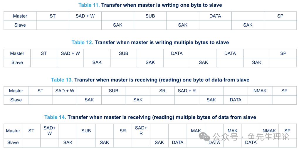 • The chart shows the communication protocol agreements between the master and slave under four communication conditions
- • Single-byte write
- • Multi-byte write
- • Single-byte read
- • Multi-byte read
For example:
- • The master is like a teacher
- • A group of I2C interfaces is like a classroom
- • The slaves connected in parallel are like students sitting in the classroom
The teacher can speak to all students, but most of the time, it is a one-on-one conversation between the teacher and one student, while the other students remain silent. During the data reading period, data may be lost.
The following describes the process of reading and writing multiple bytes
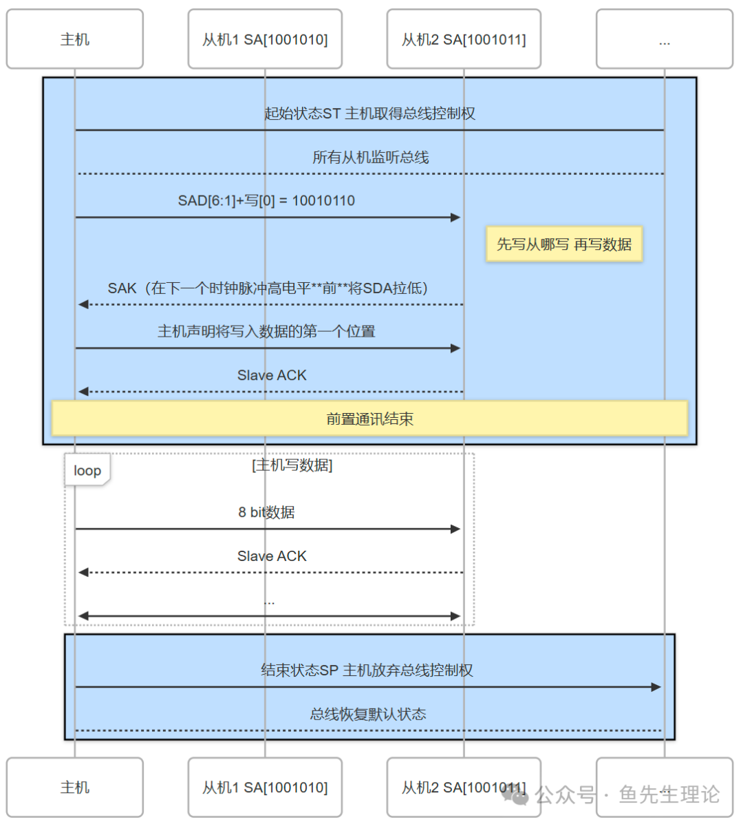
Master Writing Multi-byte Data Process
- • The classroom is silent—both wires are at a default high level
- • The teacher says, “I am going to speak now”—the master initiatesStart Condition ST (when SCL is high, pulling SDA down creates a falling edge) all slaves listen
- • The teacher calls out, “Zhang San, I want you to take notes”—the master sends the slave address “SAD[6:1]” + the last bit isthe write command “SAD[0]/W=0”
- • Zhang San replies, “I heard you”—the slave replies SAK (pulling SDA low before the next clock pulse goes high)
- • The teacher says, “Starting from page 100 of the notebook”—the master declares the first position to write data
- • Zhang San replies, “I heard you”—the slave replies SAK
- • “Write a set of data 50″—the master declares the data value to be written at the first address
- • Zhang San replies, “I heard you”—the slave replies SAK
- • “Write a set of data 51″—the master declares the data value to be written at the second address
- • Zhang San replies, “I heard you”—the slave replies SAK
- • The teacher says, “It’s over”—the master initiatesStop Condition SP (when SCL is high, pulling SDA up creates a rising edge)
- • The classroom is silent—both wires return to the default high level
SA — Slave Address (only 7 bits)
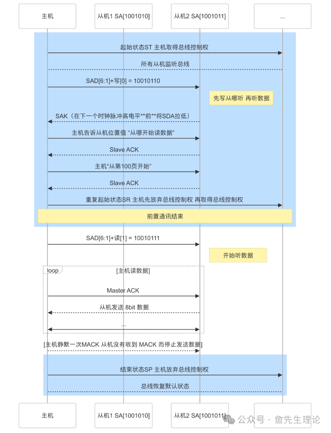
Master Reading Multi-byte Data Process
- • The classroom is silent—both wires are at a default high level
- • The teacher says, “I am going to speak now”—the master initiatesStart Condition ST (when SCL is high, pulling SDA down creates a falling edge) all slaves listen
- • The teacher calls out, “Zhang San, I want you to read a segment of numbers”—the master sends the slave address “SAD[6:1]” + the last bit isthe write command “SAD[0]/W=0”
- • Zhang San replies, “I heard you”—the slave replies SAK (pulling SDA low before the next clock pulse goes high)
- • The teacher says, “Turn to…”—the master declares the starting address to read data
- • Zhang San replies, “I heard you”—the slave replies SAK
- • “Page 100″—the master specifies the starting address value to read data
- • Zhang San replies, “I heard you”—the slave replies SAK
- • The teacher says, “Everyone be quiet”—the master initiatesRepeated Start Condition SR= actually restores the default state + ST start condition
[The slave does not need SAK]
- • SCL releases SDA before the clock pulse goes high, SDA goes high
- • When SCL is high during the clock pulse, both lines have a momentto restore the default state (high level).
- • Immediately after that, the master initiates another Start Condition ST (SDA creates a rising edge)
- • The teacher says, “Zhang San, you start reading”—the master sends the slave address “SAD[6:1]” + the last bit isthe read command “SAD[0]/R=1”
- • Zhang San replies, “I heard you”—the slave replies SAK
- • Zhang San says, “50”—the slave sends 1 byte of data
- • The teacher replies, “I heard you”—the master replies MAK (pulling SDA low before the next clock pulse goes high)
- • Zhang San says, “51”—the slave sends 1 byte of data
- • The teacher replies, “I heard you”—the master replies MAK
- • Zhang San says, “52”—the slave sends 1 byte of data
- • The teacher does not speak, and the students stop reading data—the slave does not receive MAK and stops sending data
- • The teacher says, “It’s over”—the master initiatesStop Condition SP (when SCL is high, pulling SDA up creates a rising edge)
- • The classroom is silent—both wires return to the default high level
Important Considerations
- • Each data transmission is 8 bits, with the highest bit sent first
- • SDA data is invalid when SCL is low; when SCL is high, SDA data remains unchanged.
- • Only the master can initiate
these three states; other situationsare not allowed to change SDA level when SCL is high, otherwise it will trigger these three states, leading to communication confusion.
- • Start Condition ST
- • Stop Condition SP
- • Repeated Start Condition SR
- • The slave cannot actively speak; all conversations are initiated by the master.
- • After the master finishes sending, it needs to release SDA to ensure the default state (high level), allowing the slave to correctly send SAK
- • In some cases, the slave does not send SAK (does not pull SDA low before the next clock pulse goes high), indicating the slave is busy, which is NSAK
When Not to Use I2C
- • If you do not mind a few more wires on the PCB and need a faster data reading frequency
- • Poor real-time performance: Communication can only occur one-on-one with one slave at a time; other slaves must remain silent, and data may be lost during the master’s reading period.
- • High communication overhead: Each time, the slave address must be declared, and after sending 1 byte, it must wait for 1 bit ACK, leading to low efficiency. At lower speeds, the effective data transmitted in a relative unit of time is very small; as seen in the above diagram, “pre-communication preparation” occupies part of the communication capacity.
- • If multiple masters need to access the slave chip
- • Poor robustness: If the bus is pulled low due to an anomaly (last clock pulse lost, a chip times out, SCL locked low, etc.), the master loses control, and the entire communication pauses.
- • Complex arbitration for multi-master devices: The master must quickly re-arbitrate control after losing bus control to prevent data loss or reporting errors.
- • High software overhead: Simple hardware, complex software. Requires complete fault tolerance, arbitration, bus monitoring, error correction, data encryption, and checksum algorithms.
- • If confidentiality is required and the data collected by the slave is sensitive
- • Bus Hijacking: The slave does not verify the master’s identity, making it easy to impersonate the master and read data from other slaves.