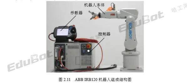
Industrial robots generally consist of three parts: the robot body, controller, and teach pendant.
This course uses the ABB typical product IRB120 robot as an example for related introduction and application analysis, with its structural composition shown in Figure 2.11.
The robot body, also known as the manipulator, is the mechanical entity of the industrial robot, used to complete designated tasks.
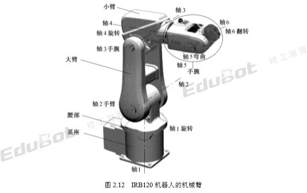
It mainly consists of robotic arm, drive unit, transmission unit, and internal sensors. For a six-axis robot, its robotic arm primarily includes the base, waist, arms (upper arm and forearm), and wrist.
The robotic arm of the IRB120 six-axis robot is shown in Figure 2.12.
In the figure, Axes 1 to 6 represent the six axes of the IRB120 robot, with arrows indicating the positive direction of rotation around the reference axis.
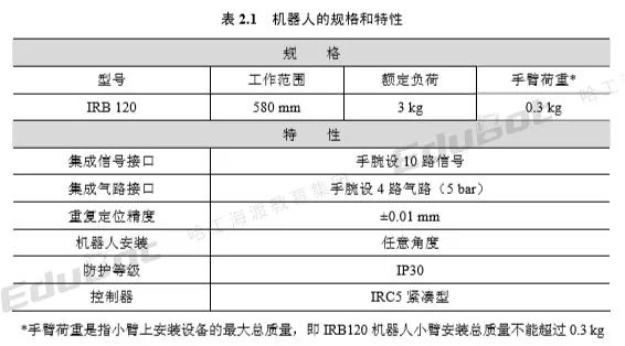
The specifications and characteristics of the IRB120 robot are shown in Table 2.1.
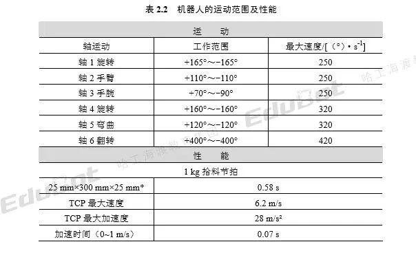
The motion range and performance of the robot are shown in Table 2.2.
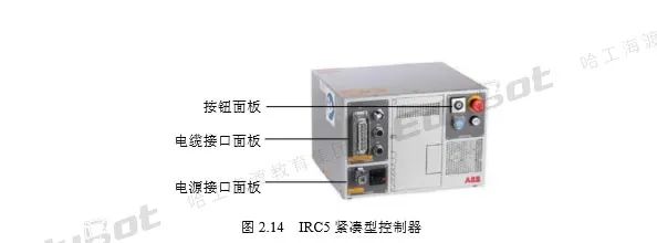
The IRB120 robot typically uses the IRC5 compact controller, which has an operation panel divided into three parts: button panel, cable interface panel, and power interface panel, as shown in Figure 2.14.
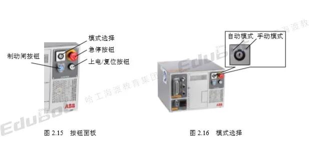
1) Button Panel (CONTROL) The names of the buttons on the button panel are shown in Figure 2.15.
There are two types of mode selection: automatic mode and manual mode, as shown in Figure 2.16.
Automatic Mode: Used during production operations, in this state, the joystick is disabled.
Manual Mode: In manual mode, the robot can only operate at low speed, manually controlled.
(2) Emergency Stop Button (Red).
No matter which mode, once the emergency stop button is pressed, the robot immediately stops operating.
(3) Power/Reset Button (White).
Indicates the power status of the motor. When the robot’s motor is activated, this button’s light is always on.
Always On: Ready, executing the program.
Blinking: The robot is unsynchronized, and the motor is not activated.
The robot brake release unit. When powered, pressing this button allows manual rotation of any axis of the robot.
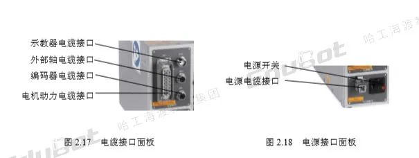
2) Cable Interface Panel (CABLE) The cable interface panel is shown in Figure 2.17, with the names and purposes of each interface as follows:
XS1: Motor power cable interface, connects to the robot’s servo motor.
XS2: Encoder cable interface, connects to the robot’s servo motor encoder.
XS4: Teach pendant cable interface, connects to the robot’s teach pendant.
XS41: External axis cable interface, connects to external axes.
3) Power Interface Panel (POWER) The interfaces of the power interface panel are shown in Figure 2.18.
Power cable interface: Controller power supply interface.
Power Switch: Controller power switch. ON means on, OFF means off.
FANUC Knowledge Point 46: Opening the Teach Pendant and Creating Programs
FANUC Knowledge Point 45: Robot Import and Tool and Workpiece Addition
FANUC Knowledge Point 44: Introduction to Simulation Software and Installation Steps
FANUC Knowledge Point 43: Program Backup and Loading
FANUC Knowledge Point 42: Introduction to Robot Zero Point Return
FANUC Knowledge Point 41: Common Abnormal Events
FANUC Knowledge Point 40: Asynchronous Conveyor Detection
FANUC Knowledge Point 39: Material Handling Examples
FANUC Knowledge Point 38: Curve Motion Examples
FANUC Knowledge Point 37: Arc Motion Examples
FANUC Knowledge Point 35: How to Execute Automatic Operation of the Robot
FANUC Knowledge Point 34: How to Test Robot Operation
FANUC Knowledge Point 33: How to Properly Execute Programs
FANUC Knowledge Point 32: How to Stop and Resume Programs
FANUC Knowledge Point 31: Essential Skills for Program Operation
FANUC Knowledge Point 30: How to Modify Industrial Robot Programs
FANUC Knowledge Point 29: Program Creation
FANUC Knowledge Point 28: Program Composition
FANUC Knowledge Point 27: Coordinate System Instructions and FOR-ENDFOR Instructions
FANUC Knowledge Point 26: Conditional Transfer, Skip Conditions, and Position Compensation Conditions Instructions
FANUC Knowledge Point 25: Wait Instructions and Unconditional Transfer Instructions
FANUC Knowledge Point 24: I/O Instructions
FANUC Knowledge Point 23: Register Instructions
FANUC Knowledge Point 22: Robot Motion Instructions
FANUC Knowledge Point 21: Operation Panel IO and Safety Signals
FANUC Knowledge Point 20: EE Interface
FANUC Knowledge Point 19: Peripheral Device IO Allocation
FANUC Knowledge Point 18: Mainboard Hardware and General I-O Allocation
FANUC Knowledge Point 17: Types of IO
FANUC Knowledge Point 16: Steps to Establish User Coordinate System
FANUC Knowledge Point 15: Principles of Establishing User Coordinate System
FANUC Knowledge Point 14: Tool Coordinate System Verification
FANUC Knowledge Point 13: Principles and Steps for Establishing Tool Coordinate System
FANUC Knowledge Point 12: Manual Manipulation of the Robot
FANUC Knowledge Point 11: Types of Coordinate Systems
FANUC Knowledge Point 10: Event Log
FANUC Knowledge Point 09: Teach Pendant Screen
FANUC Knowledge Point 08: Teach Pendant Language Settings
FANUC Knowledge Point 07: Teach Pendant Hardware Introduction
FANUC Knowledge Point 06: Robot Assembly
FANUC Knowledge Point 05: Robot Project Implementation Process and System Composition
FANUC Knowledge Point 04: Safety Operation Precautions and Introduction to FANUC Robots
FANUC Knowledge Point 03: Applications of Industrial Robots
FANUC Knowledge Point 02: Main Technical Parameters of Industrial Robots
FANUC Knowledge Point 01: Definition and Characteristics of Industrial Robots