Taking Fanuc robots as an example!
1 Unable to power on
|
Check and Repair |
Controller Components |
|
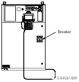
Check 1: The controller circuit breaker is on and has not tripped Repair: Reset the circuit breaker |
|
|
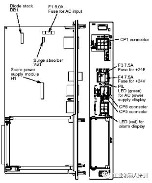
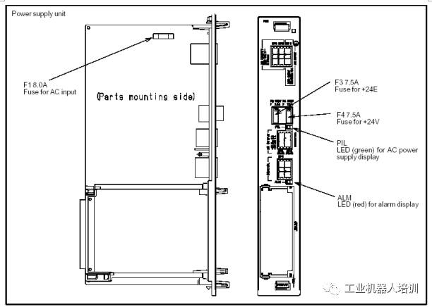
Check 2: Check if the LED indicator on the power supply board (PSU) is lit (GREEN). Repair: If the LED indicator is off, it may be that the 200V power supply for the PSU is missing or the F1 fuse on the PSU is blown: 1 If the 200V power supply is missing, please check the power supply line 2 If the 200V power supply is provided to the PSU, please disconnect the power: A If the F1 fuse is blown, refer to Repair 2 B If the F1 fuse is not blown, please replace the PSU Repair 2: Causes of fuse failure and countermeasures A Check if the CP2 and CP3 connectors between the PSU and other circuit boards are in good contact. B If the surge absorber VS1 is short-circuited, please replace itVS1 order number: A50L-2001-0122#G431K C Diode DB1 short-circuited D Backup power module H1 damaged If B or C has a fault, please replace the corresponding spare parts F1 order number: A60L-0001-0396#8.0A |
|
|
Check and Repair |
Controller Components |
|
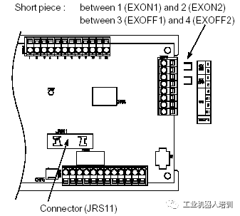
Check 3: Check the signal wiring of EXON1, EXON2, EXOFF1, EXOFF2 on the panel board Repair: If the external power switch function is not used, please short-circuit the signals EXON1 and EXON2, EXOFF1 and EXOFF2; if the external power switch function is used, please check the connection cable. |
|
|
Check 4: Check if the connection cable of JRS11 on the main board or panel board is in good contact. Check 5: Check the 1, 2, 3 above to ensure that the 200V power supply on CP1 is connected properly and the machine ON/OFF switch is normal. Please follow the steps below to check the PSU: If the LED on the PSU (ALM: red) is lit, please check if the external +24V is grounded or connected to 0V. A F4 fuse blown B Replace the PSU F4 fuse order number: A60L–0001–0046#7.5 |
|
2. Use the LED indicators on the control board to diagnose and eliminate faults
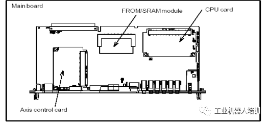
2.1 MAIN BOARD
|
Step |
Repair |
|
1 After power on, all LEDs are lit |
1 Replace the CPU card *2 Replace the MAIN BOARD |
|
2 When the robot system software starts |
1 Replace the CPU card *2 Replace the MAIN BOARD |
|
3 When the robot system starts, the CPU card DRAM initialization is complete |
1 Replace the CPU card *2 Replace the MAIN BOARD |
|
4 When the robot system starts, DRAM and SRAM initialization is complete |
1 Replace the CPU card *2 Replace the MAIN BOARD *3 Replace the FROM/SRAM card |
|
5 When the robot system starts, communication IC initialization is complete |
*1 Replace the MAIN BOARD *2 Replace the FROM/SRAM card |
|
6 When the robot system starts, the basic software loading is complete |
*1 Replace the MAIN BOARD *2 Replace the FROM/SRAM card |
|
7 When the robot powers on and starts the basic software |
*1 Replace the MAIN BOARD *2 Replace the FROM/SRAM card |
|
8 When the robot controller communicates with the TP teach pendant |
*1 Replace the MAIN BOARD *2 Replace the FROM/SRAM card |
|
9 When the robot loads the optional software |
*1 Replace the MAIN BOARD 2 Replace the process I/O board |
|
10 When initializing DI/DO |
*1 Replace the FROM/SRAM card *2 Replace the MAIN BOARD |
Replacing the MAIN BOARD and FROM/SRAM card will result in the loss of user programs and system settings stored in the machine. Be sure to back up before replacing the MAIN BOARD and FROM/SRAM card; also, make sure to back up before installing the robot system software.
|
Step |
Repair |
|
11 SRAM preparation complete |
1 Replace the axis control card *2 Replace the MAIN BOARD 3 Replace the servo amplifier |
|
12 Axis control card initialization complete |
1 Replace the axis control card *2 Replace the MAIN BOARD 3 Replace the servo amplifier |
|
13 Calibration complete |
1 Replace the axis control card *2 Replace the MAIN BOARD 3 Replace the servo amplifier |
|
14 Robot servo system powered |
*1 Replace the MAIN BOARD |
|
15 When executing the program |
*1 Replace the MAIN BOARD 2 Replace the process I/O board |
|
16 When executing I/O operations |
*1 Replace the MAIN BOARD
|
|
17 Initialization completed |
Initialization completed normally |
|
18 Robot normal |
When the robot is normal, LED1 and LED2 will flash continuously |
Replacing the MAIN BOARD and FROM/SRAM card will result in the loss of user programs and system settings stored in the machine. Be sure to back up before replacing the MAIN BOARD and FROM/SRAM card; also, make sure to back up before installing the robot system software.
|
7-segment code |
Fault description and countermeasures |
|
|
Fault: RAM parity error on the CPU card Measure 1: Replace the CPU card Measure 2: Replace the MAIN BOARD |
|
|
Fault: RAM parity error on the FROM/SRAM card Measure 1: Replace the FROM/SRAM card Measure 2: Replace the MAIN BOARD |
|
|
Fault: Communication bus error Measure 1: Replace the MAIN BOARD |
|
|
Fault: DRAM parity error during controller communication Measure 1: Replace the MAIN BOARD |
|
|
Fault: Communication error between controller and PANEL BOARD Measure 1: Check the communication cable between the MAIN BOARD and PANEL BOARD, replace it if damaged Measure 2: Replace the MAIN BOARD Measure 3: Replace the PANEL BOARD |
|
|
Fault: Servo alarm Measure 1: Replace the servo control card Measure 2: Replace the MAIN BOARD |
|
|
Fault: System emergency stop alarm Measure 1: Replace the servo control card Measure 2: Replace the CPU card Measure 3: Replace the MAIN BOARD |
|
|
Fault: System error Measure 1: Replace the servo control card Measure 2: Replace the CPU card Measure 3: Replace the MAIN BOARD |


Replacing the MAIN BOARD and FROM/SRAM card will result in the loss of user programs and system settings stored in the machine. Be sure to back up before replacing the MAIN BOARD and FROM/SRAM card; also, make sure to back up before installing the robot system software.
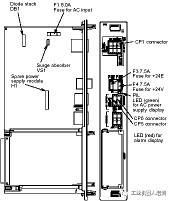
2.3 PSU LED Indicators
|
Fault description and countermeasures |
|
Fault: ALM LED (red) lit, PSU alarm Measure 1: Check the F4 (+24V) fuse on the PSU, replace if blown Measure 2: Check the +5V, +15V, +24V voltages on the PSU and the related cables and devices connected to it, replace if damaged Measure 3: Replace the PSU |
|
Fault: PIL LED (Green) not lit, PSU’s 200V power supply is missing Measure 1: Check the F1 fuse on the PSU, replace if blown Measure 2: Replace the PSU |
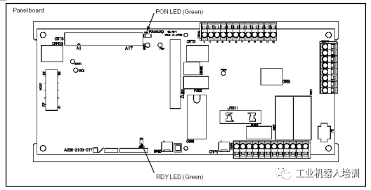
2.4 PANEL BOARD LED Indicators
|
LED |
Fault and countermeasures |
|
RDY |
Fault: This LED (GREEN) not lit indicates communication interruption between the PANEL BOARD and MAIN BOARD Measure 1: Check the communication cable between the MAIN BOARD and PANEL BOARD, replace if damaged Measure 2: Replace the MAIN BOARD Measure 3: Replace the PANEL BOARD |
|
PON |
Fault: This LED not lit indicates failure of +24V voltage conversion to +5V voltage on the PANEL BOARD Measure 1: Check the CRM63 connector, +24V input power Measure 2: Replace the PANEL BOARD |
2.5 PROCESS I/O LED Indicators
|
LED |
Fault and countermeasures |
|
Process I/O CA/CB/DA
|
Fault: Communication error between MAIN BOARD and PROCESS I/O board Measure 1: Replace the I/O board Measure 2: Replace the MAIN BOARD Measure 3: Replace the I/O communication cable |
|
Process I/O CA/CB/DA
|
Fault: I/O board fuse blown Measure 1: Replace the fuse Measure 2: Check the peripheral cables Measure 3: Replace the I/O board |
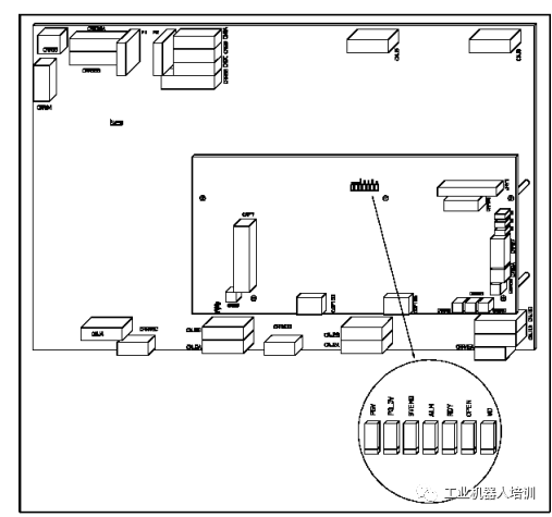
2.6 Servo Amplifier LED Indicators
|
LED |
Color |
Description |
|
P5V |
Green |
Lit: Servo amplifier +5V power supply normal Off: 1; Check the robot RP1 connection cable 2; Replace the servo amplifier |
|
P3.3V |
Green |
Lit: Servo amplifier +3.3V power supply normal Off: Replace the servo amplifier |
|
SVEMG |
Red |
Lit: The robot has an emergency stop signal input (replace if no emergency stop signal input) Off: Robot normal (replace servo amplifier if there is an emergency stop signal) |
|
ALM |
Red |
Lit: Servo amplifier fault alarm |
|
RDY |
Green |
Lit: Servo amplifier ready to drive the motor Off: If the motor can operate, replace the servo amplifier |
|
OPEN |
Green |
Lit: Communication between servo amplifier and MAIN BOARD normal Off: 1; Check the communication cable between the servo amplifier and MAIN BOARD 2; Replace the servo control card 3; Replace the servo amplifier |
|
WD |
Red |
Lit: 1; Replace the servo amplifier 2; Replace the servo control card 3; Replace the CPU card 4; Replace the MAIN BOARD |
|
D7 |
Red |
Lit: 1; Check internal cables of the controller 2; Replace the emergency stop board 3; Replace the servo amplifier |
Compiled by Ji Ge, please indicate the source when reprinting.
Link: How to Become an Industrial Robot Application Engineer?
Link: How to Become an Industrial Robot Application Engineer?
Link: How to Become an Industrial Robot Application Engineer?
We are not just porters of dry goods

Just a step away from becoming an industrial robot master
Guidance Vehicle Robot Academy, cradle of robotic craftsmen
< Previous classic articles >
-
【Dry Goods】Introduction to Fanuc Robot Electrical Hardware, Very Comprehensive!
-
【Dry Goods】Backup and Restore of Fanuc Robots, Zero Point Calibration, Essential for Engineers!
-
【Viewpoint】A Shallow Analysis of the Automation Industry, Deep Good Article!
-
Why You Shouldn’t Buy Cheap Automation Equipment?
-
Foxconn Automation Production Line Video, A Visual Feast!
-
Non-standard Automation, You Are Only One Cognition Away from the BOSS, Deep Good Article!
-
Explore the Largest Mobile Phone Manufacturer in Dongguan, The Scene After Replacing Humans with Machines!
-
China Acquires This German Company for 30 Billion, The Whole of Europe is in a Panic…
-
Huawei Automation Production Line, Shocking!
-
Automated Conveyor Belts, So Advanced!
-
Fully Automated Cigarette Production Line, Amazing to Watch!
-
Working Principles of Various Sensors in Animated GIFs, Dry Goods!
-
10 Workers + 386 Robots, 80 Cadillacs Every Day!
-
Automation in Killing Chickens and Pigs is Nothing, Come and See Automation in Killing Fish!
-
Five Major Misconceptions in Factory Automation Transformation, Don’t Make Them!