
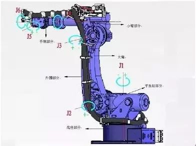
If humans only had senses and muscles, their limbs could not move. This is because, on one hand, the signals from the senses have no organs to receive and process them, and on the other hand, there are no organs to emit nerve signals that drive the muscles to contract or relax. Similarly, if a robot only has sensors and actuators, its mechanical arm cannot function properly. The reason is that the signals output by the sensors do not take effect, and the motors do not receive the driving voltage and current. Therefore, a robot needs a control system composed of hardware and software.
The function of the robot control system is to receive detection signals from sensors and drive the motors in the mechanical arm according to the requirements of the operational tasks. Just as human activities depend on their own senses, the motion control of robots cannot do without sensors. Robots need sensors to detect various states. The internal sensor signals of the robot reflect the actual motion state of the mechanical arm joints, while the external sensor signals are used to detect changes in the working environment.
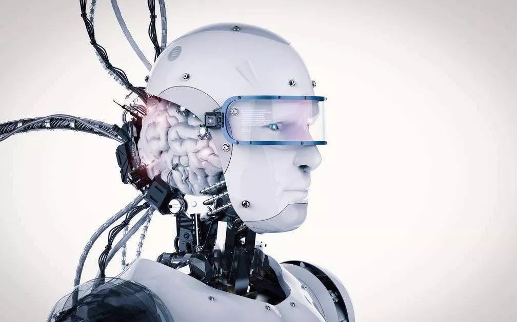
Therefore, the robot’s nerves and brain must be combined to form a complete robot control system.
Concept of Robot Control System
The robot control system refers to a management system composed of a control subject, control object, and control medium, which has its own goals and functions. A control system means that it can maintain and change any interested or variable quantity within machines, mechanisms, or other devices in the desired way. The control system is also implemented to bring the controlled object to a predetermined ideal state.
Characteristics of Robot Control System
The control technology of robots has developed based on the control technology of traditional mechanical systems, so there is no fundamental difference between the two. However, the robot control system also has many special characteristics. These characteristics are as follows:
1. The robot control system is essentially a nonlinear system. Many factors cause robot nonlinearity, including the robot’s structure, transmission components, and drive elements, which can cause system nonlinearity.
2. The robot control system is a multivariable control system consisting of multiple joints, and there is a coupling effect between each joint. Specifically, the motion of one joint will exert a dynamic effect on other joints, and each joint is subject to disturbances caused by the motion of other joints. Therefore, complex control techniques such as feedforward, compensation, decoupling, and adaptive control are often used in industrial robot control.
3. The robot system is a time-varying system, and its dynamic parameters change with the motion position of the joints.
4. More advanced robots require measurement and analysis of environmental conditions and control instructions, using computers to establish a large information database, employing artificial intelligence methods for control, decision-making, management, and operation, and automatically selecting the best control laws according to given requirements.
Basic Requirements of Robot Control System
From a usage perspective, robots are a special type of automation equipment, and their control has the following requirements:
1. Coordinated control of multi-axis motion to generate the required work trajectory. Because the movement of the robot’s hand is the composite motion of all joint movements, to make the hand move according to specified rules, it is necessary to control the coordinated actions of each joint well, including the coordination of motion trajectories and action timing.
2. High position accuracy and a large speed range. Except for Cartesian robots, the position detection elements on the robot joints are usually installed on their respective drive shafts, forming a position semi-closed-loop system. Additionally, due to the gaps in open-chain transmission mechanisms, the overall position accuracy of the robot is reduced, approximately one order of magnitude lower than that of CNC machine tools. However, the robot’s speed range is quite large, usually exceeding several thousand. This is because, during operation, the robot may process workpieces at a very low working speed; during idle travel, it can move at a very high speed to improve efficiency.
3. The static error rate of the system should be small, meaning the system must have good rigidity. This is because the robot requires smooth motion during operation, unaffected by external forces; if the static error rate is high, it will result in position errors for the robot.
4. No overshoot in position, with a fast dynamic response. Avoid collisions with workpieces while increasing system damping under the premise of ensuring appropriate system responsiveness.
5. Acceleration and deceleration control must be employed. Most robots have an open-chain structure, and their mechanical rigidity is low. Excessive acceleration and deceleration can affect their motion stability, so there should be acceleration and deceleration devices during motion start and stop. Constant acceleration and deceleration commands are usually used to achieve this.
6. The speed error coefficients of each joint should be as consistent as possible. The movement of the robot arm in space is the result of the joint movements, especially when it is required to move along a straight line or arc in space. Even if the system has tracking errors, the speed amplification factors of the servo systems for each axis joint should be as consistent as possible, and they should take larger values without affecting stability.
7. From the operator’s perspective, the control system should have a good human-machine interface and minimize the requirements on the operator. Therefore, in most cases, it is required that the designers of the controllers complete the design of the low-level servo controller while also completing the planning algorithm, and the task description should be designed in a simple language format for the user to complete.
8. From the system’s cost perspective, it is required to minimize the hardware costs of the system and to improve the performance of the control system by using more software servo methods.
Functional Requirements of Robot Control System
1. Memory function: Store work sequences, motion paths, motion modes, motion speeds, and information related to production processes.
2. Teaching function: Offline programming, online teaching, and indirect teaching. Online teaching includes teaching boxes and guided teaching.
3. Connection function with peripheral devices: Input and output interfaces, communication interfaces, network interfaces, synchronization interfaces.
4. Coordinate setting function: Four coordinate systems related to joints, absolute, tools, and user-defined.
5. Human-machine interface: Teaching box, operation panel, display screen.
6. Sensor interfaces: Position detection, vision, touch, force perception, etc.
7. Position servo functions: Multi-axis linkage, motion control, speed and acceleration control, dynamic compensation, etc.
8. Fault diagnosis and safety protection functions: Monitoring system status during operation, safety protection under fault conditions, and fault self-diagnosis.
Main Types of Robot Control Systems
The task of the control system is to control the robot’s actuators to complete movements and functions according to the robot’s operation instruction program and the signals fed back from the sensors. If the robot does not have information feedback characteristics, it is an open-loop control system; if it has information feedback characteristics, it is a closed-loop control system.
According to control principles, it can be divided into program control systems, adaptive control systems, and artificial intelligence control systems.
According to the form of motion control, it can be divided into point control and trajectory control.
Composition of Industrial Robot Control System
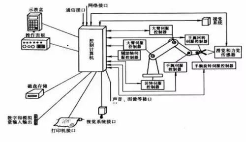
1. Control computer: The command center of the control system.
2. Teaching box: Teach the robot’s working trajectory and parameter settings, as well as all human-machine interaction operations, equipped with its own independent CPU and storage unit, achieving information exchange with the main computer via serial communication.
3. Operation panel: Composed of various operation buttons and status indicator lights, only completing basic functional operations.
4. Hard disk and floppy disk storage: Peripheral storage for storing the robot’s working program.
5. Digital and analog input/output: Input or output of various states and control commands.
6. Printer interface: Records various information that needs to be output.
7. Sensor interface: Used for automatic detection of information to achieve robot compliance control, generally including force, touch, and visual sensors.
8. Axis controllers: Complete control of the positions, speeds, and accelerations of the robot’s joints.
9. Auxiliary device control: Control of auxiliary devices that work with the robot, such as gripper positioners.
10. Communication interfaces: Achieve information exchange between the robot and other devices, generally including serial interfaces, parallel interfaces, etc.
11. Network interfaces:
1) Ethernet interface: Enables direct PC communication with multiple or single robots via Ethernet, with a data transfer rate of up to 10Mbit/s, allowing for application programming on the PC using Windows library functions, supporting TCP/IP communication protocols, and loading data and programs into each robot controller via Ethernet.
2) Fieldbus interface: Supports multiple popular field bus specifications, such as DeviceNet, ABRemoteI/O, Interbus-s, Profibus-DP, M-NET, etc.
Structure of Robot Control System
Centralized Control System
All control functions are implemented by one computer, which has a simple structure and low cost, but poor real-time performance and is difficult to expand. This structure was commonly used in early robots, as shown in the block diagram.
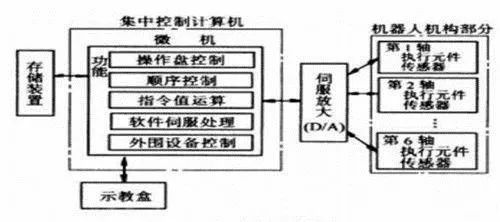
In a PC-based centralized control system, the open characteristics of PC resources are fully utilized, allowing for good openness: various control cards, sensor devices, etc., can be integrated into the control system through standard PCI slots or standard serial and parallel ports.
The advantages of a centralized control system are: lower hardware costs, ease of information collection and analysis, easier implementation of optimal control of the system, and better overall coherence and coordination, with relatively convenient hardware expansion for PC-based systems.
However, its disadvantages are also evident: the system control lacks flexibility, control hazards are easily concentrated, and once a fault occurs, the impact is wide-ranging and severe; due to the high real-time requirements of robots, when the system performs a large amount of data computation, it will reduce the real-time performance of the system, and the system’s responsiveness to multiple tasks may conflict with the real-time performance; additionally, the complex wiring of the system reduces its reliability.
Master-Slave Control Method
This method employs a two-level processor (master and slave) to realize all control functions of the system. The master CPU implements management, coordinate transformation, trajectory generation, and system self-diagnosis; the slave CPU controls the movements of all joints. The structure block diagram is shown.
The master-slave control method has good real-time performance, suitable for high-precision and high-speed control, but its system expandability is poor and maintenance is difficult.
Distributed Control Method
This method divides system control into several modules based on the nature and method of the system, each with different control tasks and strategies. The relationships between modes can be master-slave or equal. This method has good real-time performance, is easy to achieve high-speed and high-precision control, is easy to expand, and can achieve intelligent control. It is currently a popular method, as shown in the control block diagram.
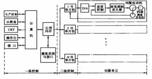
The main idea is “distributed control, centralized management”, meaning the system can comprehensively coordinate and allocate its overall goals and tasks and complete control tasks through the coordinated work of subsystems. The entire system is decentralized in terms of functionality, logic, and physically, thus also referred to as a distributed control system.
In this structure, subsystems are composed of controllers and different controlled objects or devices, and the subsystems communicate with each other via networks. Distributed control structures provide an open, real-time, and precise robot control system. In distributed systems, a two-level control method is often employed.
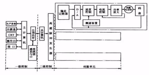
Two-Level Distributed Control System
This system typically consists of an upper computer, a lower computer, and a network. The upper computer can perform different trajectory planning and control algorithms, while the lower computer conducts research and implementation of interpolation subdivision and control optimization. The upper and lower computers coordinate their work through a communication bus, which can take forms such as RS-232, RS-485, EEE-488, and USB bus.
Now, the development of Ethernet and fieldbus technology provides robots with faster, more stable, and effective communication services. Especially the fieldbus, which is applied in production sites to achieve bidirectional multi-node digital communication between microcomputer measurement and control devices, forming a new type of network-integrated fully distributed control system—fieldbus control system.
The advantages of distributed control systems include: good system flexibility, reduced danger of control systems, and the use of multi-processor distributed control, which is conducive to parallel execution of system functions, improving processing efficiency and shortening response time.
Classification of Robot Control Systems
1. Program control system: Applies a certain rule of control to each degree of freedom, allowing robots to achieve the required spatial trajectory.
2. Adaptive control system: When external conditions change, this system ensures the required quality or improves control quality based on experience accumulation, adjusting the parameters of a nonlinear model until the error disappears. The structure and parameters of this system can change automatically over time and conditions.
3. Artificial intelligence system: Does not have a pre-compiled motion program but requires real-time determination of control actions based on the surrounding state information obtained during movement.
4. Point control system: Requires the robot to accurately control the pose of the end effector, irrespective of the path.
5. Continuous trajectory control system: Requires the robot to move according to the taught trajectory and speed.
6. Control bus: International standard bus control system. Uses international standard buses as control buses for the control system, such as VME, MULTI-bus, STD-bus, and PC-bus.
7. Custom bus control system: A bus defined by the manufacturer for use as the control system bus.
8. Programming method: Physically set programming system. The operator sets fixed limit switches to implement start and stop program operations, which can only be used for simple pick-and-place tasks.
9. Online programming: Programming method that completes the memory process of operational information through human teaching, including direct teaching, simulated teaching, and teaching box teaching.
10. Offline programming: Does not directly teach the robot in the actual working environment but generates teaching programs by using advanced robots, programming languages, and remote offline generation of the robot’s work trajectory.
This article is sourced from: Sensor Technology