PROFIBUS is an international, open, and device-independent fieldbus standard. The transmission speed of PROFIBUS can be selected within the range of 9.6kbaud to 12Mbaud, and when the bus system starts, all devices connected to the bus should be set to the same speed. It is widely used in manufacturing automation, process automation, and other fields such as building and traffic power automation. PROFIBUS is a fieldbus technology used for workshop-level monitoring and data communication and control at the field device layer. It enables decentralized digital control and field communication networks from the field device layer to workshop-level monitoring, providing feasible solutions for comprehensive factory automation and intelligent field devices.
The composition of the PROFIBUS bus:
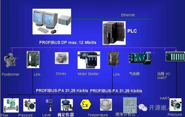
PROFIBUS stands for Process Field Bus and officially became the international standard for fieldbus in 1989. It occupies a dominant position in various automation fields, with over 20 million device nodes worldwide. It consists of three compatible parts: PROFIBUS-DP (Decentralized Periphery), PROFIBUS-PA (Process Automation), and PROFIBUS-FMS (Fieldbus Message Specification). PROFIBUS-DP is applied at the field level and is a high-speed, low-cost communication method for communication between device-level control systems and decentralized I/O. The bus cycle is generally less than 10ms, using protocols at layers 1 and 2 and user interfaces to ensure fast and effective data transmission. PROFIBUS-PA is suitable for process automation, allowing sensors and actuators to connect on a shared bus, applicable in intrinsically safe areas. PROFIBUS-FMS is used for workshop-level monitoring networks, which is a token-structured real-time multi-master network used for communication between controllers and intelligent field devices, as well as information exchange between controllers. It mainly uses a master-slave method, typically exchanging data periodically with drive devices.
The basic performance of the PROFIBUS bus:
Compared with other fieldbus systems, the greatest advantage of PROFIBUS is its stability, guaranteed by the international standard EN50170, and its universality verified by practical applications. It has been applied in fields including processing manufacturing, process control, and automation. The open and vendor-independent communication concept of PROFIBUS has been realized in over 100,000 successful applications. Market research confirms that PROFIBUS occupies more than 40% of the market for open industrial fieldbus systems in Germany and Europe. PROFIBUS is supported by internationally renowned manufacturers of automation technology equipment, each with its own technical advantages and capable of providing a wide range of high-quality new products and technical services.
The protocol structure of the PROFIBUS bus:
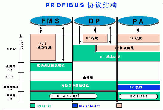
The PROFIBUS protocol structure (1) PROFIBUS-DP: defines layers one, two, and user interface. Layers three to seven are not described. The user interface specifies the application functions available to users and systems and different devices, detailing the behavior of various PROFIBUS-DP devices. (2) PROFIBUS-FMS: defines layers one, two, and seven, with the application layer including the Fieldbus Message Specification (FMS) and Lower Layer Interface (LLI). FMS includes the application protocol and provides users with powerful communication services that can be widely selected. LLI coordinates different communication relationships and provides a device-independent second-layer access interface. (3) PROFIBUS-PA: PA data transmission uses the extended PROFIBUS-DP protocol. In addition, PA describes the behavior of field devices according to IEC1158-2 standards, ensuring intrinsic safety and allowing power supply to field devices via the bus. Connectors can be used to extend the PA network on the DP. PROFIBUS transmission technology provides three types of data transmission: · RS485 transmission for DP and FMS. · IEC1158-2 transmission for PA. · Optical fiber.
RS485 transmission technology for DP/FMS:
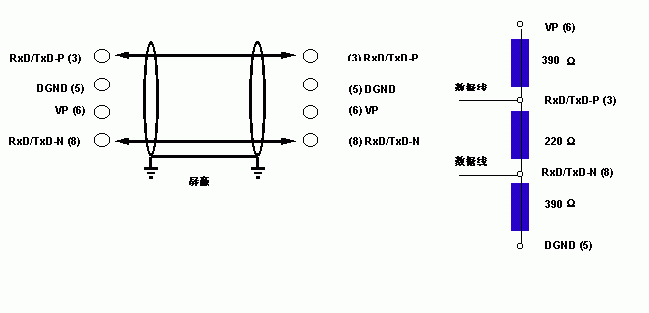
Since DP and FMS systems use the same transmission technology and unified bus access protocol, both systems can operate simultaneously on the same cable. RS-485 transmission is the most commonly used transmission technology for PROFIBUS. This technology is typically referred to as H2. The cable used is a shielded twisted pair copper wire. Basic features of RS-485 transmission technology include: · Network topology: linear bus, with active bus termination resistors at both ends. · Transmission rate: 9.6K bit/s to 12M bit/s. · Medium: shielded twisted pair cable, which can also be unshielded depending on environmental conditions (EMC). · Number of stations: 32 stations per segment (without repeaters), up to 127 stations (with repeaters). · Connector: best to use a 9-pin D-type connector.
Installation points for RS-485 transmission devices:
(1) All devices are connected to the bus. (2) A maximum of 32 stations (master or slave) can be connected per segment. (3) Each segment has a bus termination resistor at both ends to ensure error-free operation. Both bus termination resistors must always have power. (4) When the number of stations exceeds 32, repeaters must be used to connect each bus segment. Generally, no more than three repeaters in series.
PROFIBUS-DP system configuration and device types:
PROFIBUS-DP allows the formation of single-master or multi-master systems. Up to 126 stations can be connected on the same bus. The system configuration description includes: number of stations, station addresses, input/output addresses, input/output data formats, diagnostic information formats, and the bus parameters used. Each PROFIBUS-DP system may include the following three different types of devices: (1) Level 1 DP Master (DPM1): the level 1 DP Master is the central controller that exchanges information with decentralized stations (such as DP slaves) within a predetermined information cycle. Typical DPM1s include PLCs or PCs. (2) Level 2 DP Master (DPM2): the level 2 DP Master is a programmer, configuration device, or operation panel used during DP system configuration operations to achieve system operation and monitoring purposes. (3) DP Slave: DP slaves are peripheral devices (I/O devices, drivers, HMIs, valves, etc.) that collect and send input and output information. (4) Single-master system: during the operation phase of the bus system, there is only one active master. (5) Multi-master system: multiple masters are connected to the bus. These masters form independent subsystems with their respective slaves. Each subsystem includes one DPM1, a specified number of slaves, and possibly DPM2 devices. Any master can read the input/output image of the DP slaves, but only one DP master is allowed to write data to the DP slaves.
Data transmission cycle between DPM1 (Master) and DP Slaves : Data transmission between DPM1 and the associated DP slaves is automatically performed by DPM1 in a determined recursive order. When configuring the bus system, the user specifies the relationship between the DP slaves and DPM1, determining which DP slaves are included in the information exchange cycle and which are excluded. The data transfer between DPM1 and DP slaves occurs in three stages: parameter setting, configuration, and data exchange. In the parameter setting stage, each slave compares its actual configuration data with the configuration data received from DPM1. Only when the actual data matches the required configuration data does the DP slave enter the user data transmission stage. Therefore, the device type, data format, length, and input/output quantity must match the actual configuration. There are many types of transmission modes and communication data protection modes for the PROFIBUS bus. Here, only a brief introduction is provided. PROFIBUS is widely used, and specific implementation schemes are simple, stable, and reliable. For detailed design information, please contact us for the scheme.
Our official QQ group: 281549832
We would like to thank everyone for their strong support!