Click the image above to follow “Chuangxue Electronics” and easily learn electronic knowledge.
A universal circuit board is a printed circuit board filled with pads according to the standard IC spacing (2.54mm), allowing users to insert components and connect wires as desired, commonly known as a “breadboard.” Compared to professional PCB fabrication, breadboards have the following advantages: low entry barrier, low cost, convenient to use, and flexible expansion. For example, in college electronic design competitions, projects often need to be completed in a race against time within a few days, so most use breadboards.
Choosing a Breadboard
Currently, there are mainly two types of breadboards on the market: one with independent pads (Figure 1, hereinafter referred to as single-hole boards) and the other with multiple pads connected together (Figure 2, hereinafter referred to as connected-hole boards). Single-hole boards can be divided into single-sided and double-sided boards. In my experience, single-hole boards are more suitable for digital circuits and microcontroller circuits, while connected-hole boards are better for analog circuits and discrete circuits. This is because digital circuits and microcontroller circuits mainly focus on chips, which are more regular; whereas analog circuits and discrete circuits tend to be less regular. The pins of discrete components often need to connect multiple wires, so having multiple pads connected together is more convenient. Of course, this is not absolute; everyone has different preferences, so just choose what works best for you.
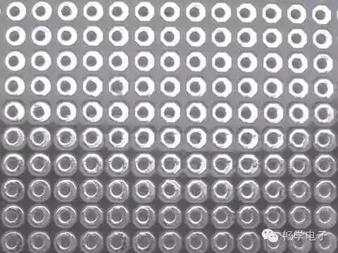
Figure 1 Single-hole Board
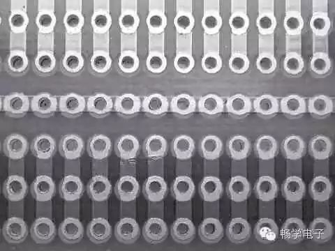
Figure 2 Connected-hole Board
Additionally, readers need to distinguish between two different materials of breadboards: copper boards and tin boards. The pads on copper boards are exposed copper, appearing golden yellow, and should be stored wrapped in paper to prevent oxidation. If the pads oxidize (losing luster and becoming difficult to solder), they can be cleaned with a cotton swab dipped in alcohol or wiped with an eraser. The pads on tin boards are coated with a layer of tin, appearing silver-white; the substrate material of tin boards is harder than that of copper boards and is less prone to deformation. Their prices also differ; for example, a single-sided board sized 100 cm2 (10cm×10cm) costs about 3-4 yuan for copper boards and 7-8 yuan for tin boards, generally not exceeding 0.08 yuan per square centimeter.
Preparation Before Soldering
Before soldering on a breadboard, it is necessary to prepare enough fine wires (Figure 3) for wiring. Fine wires can be single-stranded or multi-stranded (Figure 4): single-stranded hard wires can be bent into fixed shapes and used as jumpers after stripping; multi-stranded fine wires are soft and appear messy after soldering.
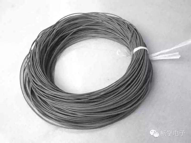
Figure 3 Fine Wires
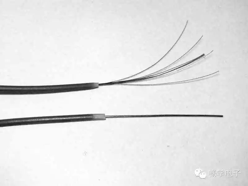
Figure 4 Multi-stranded and Single-stranded Fine Wires
Breadboards have tightly spaced pads, which requires our soldering iron tip to have high precision. It is recommended to use a soldering iron with a power of about 30W. Similarly, the solder wire should not be too thick; it is recommended to choose a wire diameter of 0.5-0.6mm.
Soldering Methods for Breadboards
For the layout of components on the breadboard, most people are accustomed to the method of “following the vines to find the melons,” which means centering around key components like chips and inserting other components in the gaps. This method allows for planning while soldering, reflecting order amid chaos, and is quite efficient. However, due to a lack of experience, beginners may find this method unsuitable. Beginners can first make a preliminary layout on paper, then draw it on the front (component side) of the breadboard with a pencil, which also allows for planning the wiring, making soldering easier.
The soldering method for breadboards generally involves using the fine wires mentioned earlier for flying connections. Flying connections do not require much technique, but should be as horizontal and vertical as possible for neatness (Figure 5). There is currently a popular method online called the solder-joint wiring method, as shown in Figure 6; it has good craftsmanship and stable performance but tends to waste solder. Pure solder-joint wiring is more difficult and is influenced by factors such as solder wire and individual soldering skills. If you first pull a fine copper wire and then drag solder along the fine copper wire, it becomes much easier. The soldering method for breadboards is quite flexible, and everyone can find a method that suits them.
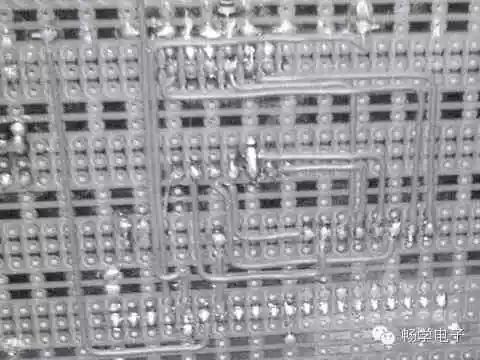
Figure 5 Common Flying Connection Method
Soldering Techniques for Breadboards
Many beginners find that their soldered boards are unstable, prone to short circuits or open circuits. Besides poor layout and soldering quality, lack of skills is one of the important reasons for these issues. Mastering some techniques can significantly reduce the complexity of reflecting circuits onto physical hardware, minimize the number of flying wires, and stabilize the circuit. Below are some soldering techniques for breadboards based on my experience.
1. Preliminary Layout of Power and Ground Wires
The power supply runs through the entire circuit, and a reasonable power layout plays a crucial role in simplifying the circuit. Some breadboards have copper foil running through the entire board, which should be used as power and ground wires; if there is no such copper foil, you also need to have a preliminary plan for the layout of power and ground wires.
2. Utilize Component Pins Wisely
Soldering on a breadboard requires a lot of bridging and jumpers; don’t rush to cut off excess pins of components. Sometimes bridging directly to the pins of surrounding components can be much more efficient. Additionally, in the spirit of material conservation, you can collect cut-off component pins to use as jumper materials.
3. Be Generous with Jumpers
This point is particularly important; using more jumpers not only simplifies wiring but also looks much neater, as shown in Figure 7.
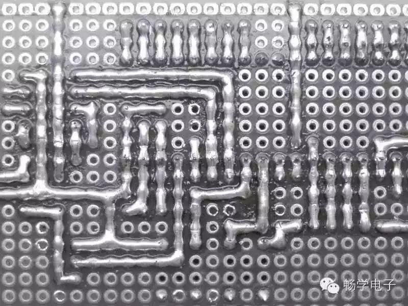
Figure 6 Solder-joint Wiring Method
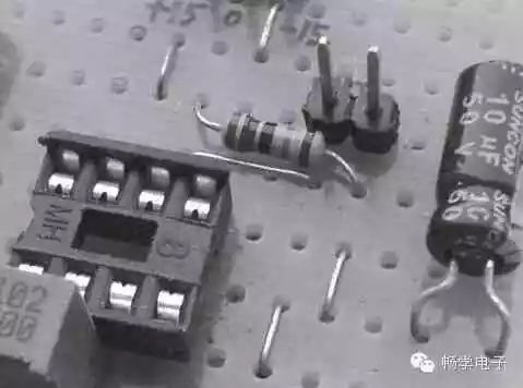
Figure 7 Use More Jumpers
4. Utilize the Structure of Components
Figure 8 shows a matrix keyboard circuit, while Figure 9 shows a matrix keyboard that I soldered. This is a typical example of utilizing the structure of components: the tactile switches in Figure 9 have four pins, with two pairs connected; we can use this feature to simplify wiring, as the electrically connected two pins act as jumpers. Readers can refer to Figure 10 for a better understanding.
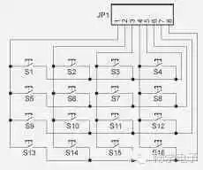
Figure 8 Matrix Keyboard Circuit
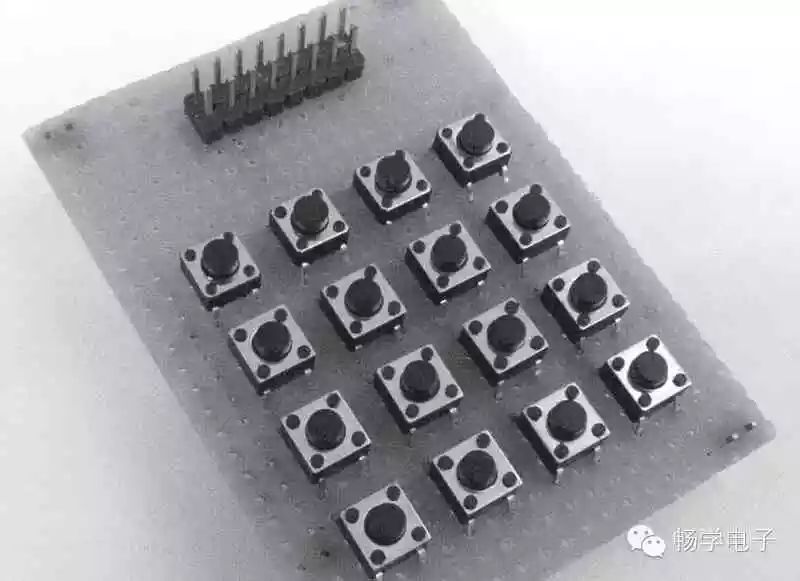
Figure 9 Matrix Keyboard
5. Make Good Use of Pin Headers
I prefer using pin headers because they have many flexible applications. For example, when connecting two boards, pin headers and sockets can be used. Pin headers serve both mechanical and electrical connection purposes between the two boards. This method is inspired by computer board connections.
6. Cut Copper Foil When Necessary
When using connected-hole boards, to make full use of space, it may be necessary to cut certain copper foils with a knife, allowing for more components to be placed in limited space.
7. Make Full Use of Double-sided Boards
Double-sided boards are relatively expensive, so if you choose them, you should make full use of them. Each pad on a double-sided board can act as a via, flexibly achieving electrical connections on both sides.
8. Optimize the Use of Space on the Board
Chip sockets can hide components, making it both aesthetically pleasing and protective of the components (Figure 11).
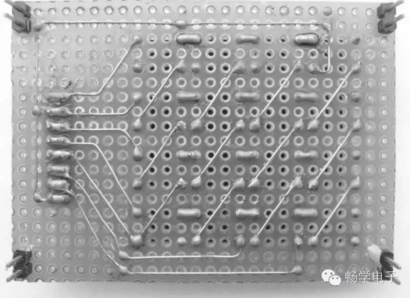
Figure 10 Back of Matrix Keyboard
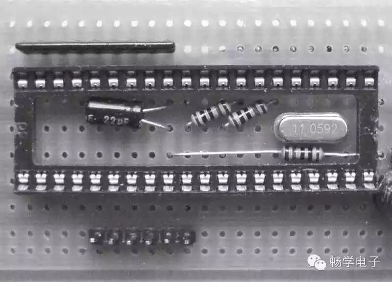
Figure 11 Components Hidden Inside Chip Socket
“Breadboards” have brought us great convenience; perhaps they have become an indispensable part of your electronic experiments. By referring to these tips I’ve provided and practicing more, you will discover better and more suitable methods and techniques for your use.
> > > > > > > > > > > > > > > > > > > > > > > > > > > > > > > > > > > > > > > > > > > > > > > > > > > > > >
==> Go to www.eeskill.com to learn more!