1
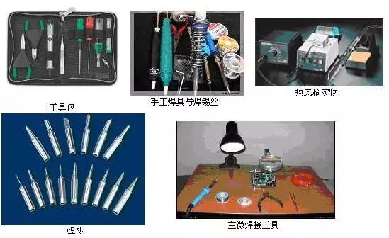
Tools for Manual Soldering
Any electronic product, from a rectifier composed of several parts to a computer system made up of thousands of components, is constructed from basic electronic components and functions, connected using certain manufacturing methods according to circuit principles.Although there are various connection methods (such as winding, crimping, gluing, etc.), the most widely used method is soldering.
Tools for Manual Soldering
-
Electric Soldering Iron
-
Chromium Iron Stand
Conditions for Soldering
-
The soldered component must possess solderability.
-
The surface of the metal to be soldered should remain clean.
-
Use appropriate flux.
-
Maintain appropriate soldering temperature.
-
Maintain appropriate soldering time.
2
Solder and Flux
Common Solder Materials
-
Tubular Solder Wire
-
Oxidation-Resistant Solder
-
Silver-Containing Solder
-
Solder Paste
Choosing Flux
During the soldering process, a thin layer of oxide film forms on the metal due to heating, which hinders the wetting of the solder and affects the formation of the solder joint alloy, easily leading to cold soldering and false soldering.
Using flux can improve soldering performance. Fluxes include rosin, rosin solutions, solder paste, and solder oils, which should be selected appropriately based on different soldering objects. Solder paste and solder oils have a certain degree of corrosiveness and should not be used for soldering electronic components and circuit boards. After soldering, any residual solder paste or solder oil should be cleaned off. When soldering component leads, rosin should be used as the flux. If the printed circuit board has already been coated with rosin solution, there is no need to use additional flux when soldering components.
3
Precautions for Manual Soldering
Manual tin soldering technology is a basic skill that must be used for maintenance and repair even in large-scale production.Therefore, it is necessary to learn and practice to master it proficiently.The precautions are as follows:
Correct Hand Position for Holding the Soldering Iron
Mastering the correct hand position for holding the soldering iron can ensure the operator’s physical and mental health and reduce labor injuries.To minimize the harmful effects of chemical substances that evaporate during heating, and to reduce the inhalation of harmful gases, the distance from the soldering iron to the nose should generally be no less than 20 cm, with 30 cm being preferable.
There are three ways to hold the soldering iron, as shown in the figure below.
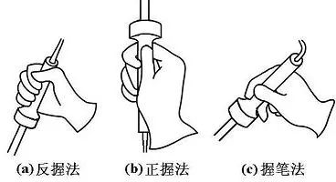 Method of holding the soldering iron
The reverse grip method is stable and does not easily cause fatigue during long operations, suitable for high-power soldering iron operations; the forward grip method is suitable for low-power soldering irons or soldering irons with bent tips; generally, the pen grip method is often used when soldering printed circuit boards on a workbench.
Correct Hand Position for Holding Solder Wire
Solder wire generally has two ways of holding, as shown in the figure below.Since solder wire contains a certain proportion of lead, which is a harmful heavy metal to the human body, gloves should be worn during operation or hands should be washed after operation to avoid ingesting lead dust.
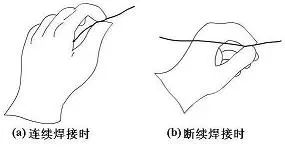 Method of holding solder wire
After using the electric soldering iron, it must be securely placed on the soldering iron stand, and care should be taken to ensure that wires and other debris do not touch the soldering iron tip to prevent burns and leakage accidents.
4
Basic Steps for Manual Soldering
Mastering the temperature of the soldering iron and soldering time, selecting the appropriate soldering iron tip and the contact position of the solder joint, is essential for achieving good solder joints. The correct manual soldering process can be divided into five steps, as shown in the figure.
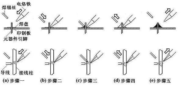 Steps for Manual Soldering
Basic Operating Steps
-
Preparing to Solder (Figure (a)): Hold the solder wire in the left hand and the soldering iron in the right hand, entering the soldering state. The soldering iron tip should remain clean, free of solder dross and other oxides, and coated with a layer of solder.
-
Heating the Solder Joint (Figure (b)): The soldering iron tip rests on the connection point of the two soldered components, heating the entire solder joint for about 1 to 2 seconds. When soldering components on a printed circuit board, ensure that the soldering iron tip simultaneously contacts both soldered objects. For example, the wire in Figure (b) should simultaneously and evenly heat the connection point with the terminal and the component lead with the pad.
-
Feeding in Solder (Figure (c)): When the solder joint has reached a certain temperature, feed the solder wire from the opposite side of the soldering iron to the solder joint. (Note: Do not feed the solder wire onto the soldering iron tip.)
-
Removing the Solder Wire (Figure (d)): Once a certain amount of solder has melted, immediately move the solder wire away at a 45° angle to the upper left.
-
Removing the Soldering Iron (Figure (e)): After the solder has wetted the pad and the solder joint area, move the soldering iron away at a 45° angle to the upper right to finish the soldering. The time from the third step to the fifth step should also be about 1 to 2 seconds.
Three-Step Soldering Method
For solder joints with low thermal capacity, such as connections on printed circuit boards with thin wires, the process can be simplified into three steps.
-
Preparation: Same as step one above.
-
Heating and Feeding Solder: Place the soldering iron tip on the solder joint and immediately feed in solder.
-
Remove Solder and Soldering Iron: Once the solder has wetted and spread to the desired area on the solder joint, immediately remove the solder wire and the soldering iron, ensuring that the solder wire is removed at the same time or before the soldering iron is removed.
For solder joints with low heat absorption, the entire process time is only about 2 to 4 seconds. The control of each step’s rhythm, the accurate mastery of the sequence, and the skilled coordination of movements can only be resolved through extensive practice and careful experience.
Some have summarized a method to control time using seconds during the five-step process: after the soldering iron contacts the solder joint, count one, two (about 2 seconds), feed in the solder, count three, four, and then remove the soldering iron. The amount of solder to be melted should be determined by observation. This method can be referenced, but due to differences in soldering iron power and solder joint heat capacity, there is no fixed rule for mastering soldering timing; specific conditions must be treated specifically. For instance, for a solder joint with a large heat capacity, if a low-power soldering iron is used, the temperature may not be sufficient to melt the solder within the specified time, making soldering impossible.
5
Specific Techniques for Manual Soldering
While ensuring high-quality solder joints, specific soldering techniques may vary, but the following methods summarized by predecessors are invaluable for beginners.
Keep the Soldering Iron Tip Clean
During soldering, the soldering iron tip remains at a high temperature for extended periods and comes into contact with flux and other weakly acidic substances, making it prone to oxidation and corrosion, accumulating a layer of black impurities.These impurities form an insulating layer that hinders heat transfer between the soldering iron tip and the solder joint.Therefore, it is crucial to wipe the soldering iron tip with a damp cloth or a damp wooden fiber sponge regularly.For ordinary soldering iron tips, if there is severe corrosion and contamination, a file can be used to remove the oxidized layer. However, this method should never be used on long-life soldering iron tips.
Increase Contact Area to Accelerate Heat Transfer
When heating, the solder joint should be evenly heated in all areas that need solder, rather than just heating one part of the solder joint. Additionally, do not apply pressure with the soldering iron on the solder joint, as this may cause damage or unnoticed hazards.Some beginners apply pressure with the soldering iron tip on the solder joint, attempting to speed up soldering, which is incorrect.The right method is to select different soldering iron tips based on the shape of the solder joint or to modify the soldering iron tip to create a surface contact with the solder joint rather than point or line contact.This significantly improves heat transfer efficiency.
Heating Should Rely on Solder Bridge
In non-assembly line work, solder joint shapes vary widely, making it impractical to constantly change soldering iron tips.To improve heating efficiency, a solder bridge is needed for heat transfer.A solder bridge refers to retaining a small amount of solder on the soldering iron tip, which serves as a bridge for heat transfer between the soldering iron tip and the solder joint.Since the thermal conductivity of molten solder is much higher than that of air, the solder joint is quickly heated to the soldering temperature.It should be noted that the amount of solder retained as a solder bridge should not be excessive, as prolonged retention of solder on the soldering iron tip may lead to overheating, degrading its quality and potentially causing short circuits between solder joints.
Timing of Soldering Iron Removal
The removal of the soldering iron should be timely, and the angle and direction of removal are related to the formation of the solder joint.The figure below shows how different removal directions of the soldering iron affect the amount of solder at the joint.
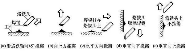 Relationship Between Soldering Iron Removal Direction and Solder Joint Quantity
Do Not Move Before Solder Solidifies
Do not move or vibrate the solder joint, especially when holding the solder joint with tweezers; wait until the solder has solidified before removing the tweezers, or it may easily cause the solder joint structure to become loose or cold soldered.
Moderate Amount of Solder
The tubular solder wire commonly used in manual soldering already contains flux made of rosin and activators.The diameter of solder wire varies, such as 0.5, 0.8, 1.0, …, 5.0 mm, and should be selected based on the size of the solder joint.Generally, the diameter of the solder wire should be slightly smaller than that of the solder pad.
As shown in the figure, excessive solder not only unnecessarily consumes solder but also increases soldering time and reduces work speed. More seriously, excessive solder can easily lead to unnoticed short circuit failures. Conversely, insufficient solder cannot form a strong bond, which is equally detrimental. This is especially true when soldering the leads of components on printed circuit boards, where insufficient solder can easily cause the lead to fall off.
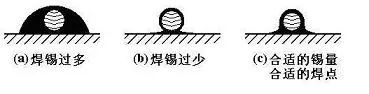
Control of Solder Quantity
Moderate Amount of Flux
A proper amount of flux is very beneficial for soldering.Excessive use of rosin flux will inevitably require cleaning off the excess after soldering, extending heating time and reducing work efficiency.When heating time is insufficient, it easily leads to defects like “slag inclusion.”When soldering switches and connectors, excessive flux can flow onto contacts, causing poor connectivity.
The appropriate amount of flux should only wet the area where the solder joint is to be formed without flowing through the through holes on the printed circuit board. For soldering with rosin-core solder wire, there is generally no need to apply additional flux. Currently, most printed circuit board manufacturers perform rosin spraying treatment before the circuit board leaves the factory, eliminating the need for additional flux.
Do Not Use the Soldering Iron Tip to Transport Solder
Some people habitually use the soldering iron tip to transport solder to the solder joint, resulting in solder oxidation.Since the temperature of the soldering iron tip is generally above 300 °C, the flux in the solder wire is prone to decompose and fail at high temperatures, and the solder is in a low-quality state due to overheating.It should be particularly noted that some outdated publications have introduced methods of transporting solder with the soldering iron tip; readers should be cautious in identifying such methods.
6
Quality and Inspection of Solder Joints
The quality requirements for solder joints should include good electrical contact, strong mechanical bonding, and aesthetic appearance.The most important point to ensure solder joint quality is to avoid cold soldering.
Causes and Hazards of Cold Soldering
Cold soldering is mainly caused by oxidation and dirt on the surface of the metal to be soldered, making the solder joint a connection state with contact resistance, leading to unstable circuit operation, intermittent connectivity, and increased noise without regularity, posing significant risks during circuit debugging, usage, and maintenance.
Moreover, some cold solder joints may maintain good contact for a long time when the circuit starts working, making them difficult to detect. However, under the influence of temperature, humidity, and vibration, the contact surface gradually oxidizes, leading to incomplete contact over time. The contact resistance of cold solder joints can cause localized heating, which further exacerbates the incomplete contact situation, ultimately causing the solder joint to fall off and the circuit to stop functioning properly.
This process can sometimes take one to two years, and its principle can be explained using the concept of a “galvanic cell”: when moisture penetrates the gap of a solder joint, water molecules dissolve metal oxides and dirt to form an electrolyte, with the copper and lead-tin solder on either side of the cold solder joint acting as the two electrodes of the galvanic cell. The lead-tin solder loses electrons and gets oxidized, while the copper gains electrons and gets reduced. In such a galvanic cell structure, corrosion occurs within the cold solder joint, and increased local temperature accelerates chemical reactions, with mechanical vibrations expanding the gaps until a vicious cycle leads to an open circuit at the cold solder joint.
Statistics show that nearly half of the faults in electronic products are caused by poor soldering. However, identifying the cold solder joints causing faults in an electronic device with thousands of solder joints is not an easy task. Therefore, cold soldering poses a significant reliability hazard for circuits and must be strictly avoided. Special attention should be paid during manual soldering operations.
In general, the main causes of cold soldering include: poor solder quality; inadequate or poor-reducing flux; unclean surfaces of the soldered parts; poor solder plating; excessively high or low temperatures of the soldering iron tip; oxidized surfaces; improper control of soldering time, either too long or too short; and movement of soldered components before the solder has solidified.
Requirements for Solder Joints
-
Reliable electrical connection
-
Enough mechanical strength
-
Neat and tidy appearance
Formation and Appearance of Typical Solder Joints
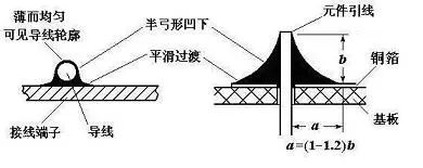
On single-sided and double-sided (multi-layer) printed circuit boards, the formation of solder joints differs: In single-sided boards, solder joints form only above the solder pads; however, on double-sided or multi-layer boards, molten solder not only wets above the solder pads but also penetrates into the metallized holes due to capillary action, with the area of solder joint formation including above the solder pads, within the metallized holes, and on parts of the pads on the component side, as shown in the figure.
 Left: Formation of Solder Joint Right: Appearance of Typical Solder Joint
As shown in the figure, a typical solder joint should have an appearance that is a near-conical shape with a slightly concave surface, forming a skirt shape symmetrically spread from the center of the soldered wire. The surface of a cold solder joint often bulges outward, making it identifiable.
On the solder joint, the solder connection surface should transition smoothly, with the boundary between the solder and the soldered component having a small contact angle; the surface should be smooth and shiny, free of cracks, pinholes, or inclusions.
Copyright Notice: The copyright of this article belongs to the original author and does not represent the views of the association. The articles promoted by the “Jiangxi Province Electronic Circuit Industry Association” are for sharing purposes only and do not represent the position of this account. If there are copyright issues, please contact us for deletion.