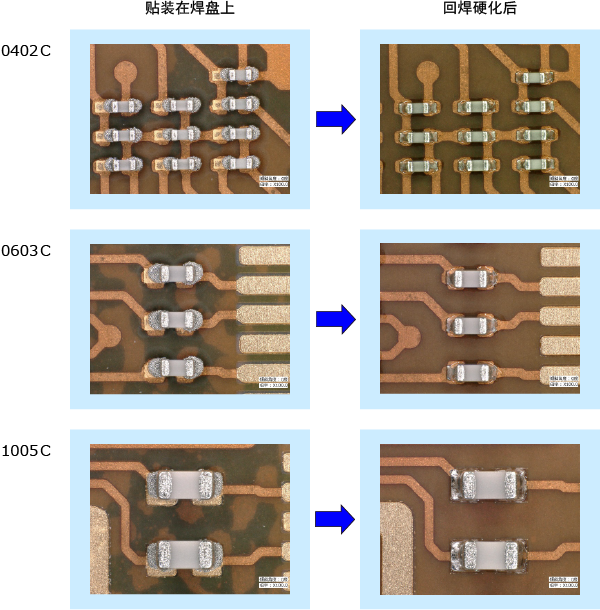
TOP Mounting
Target On Paste
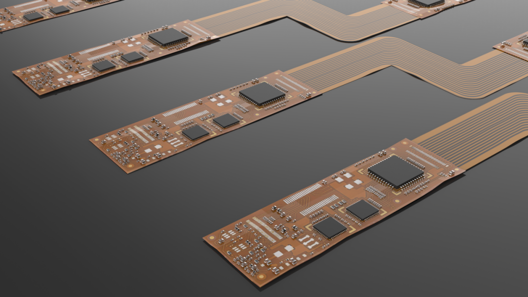
Due to the ultra-thin and flexible characteristics of FPC (Flexible Printed Circuits), it is widely used in the sliding and bending parts of small electronic devices, as well as in the three-dimensional layout of small mobile terminals like smartphones and wearable devices.
However, despite the widespread application of flexible circuit boards, the mounting quality is extremely unstable. This is because it is made of flexible film adhesive, and its main substrate, the polyimide film layer, has different flexibility from the copper foil layer, adhesive layer, and sputtering layer, which can cause wrinkles during manufacturing, leading to changes in the size of the circuit board. Additionally, the unstable accuracy of the substrate bonding leads to discrepancies in the pad position and shape compared to expectations, resulting in deviations between the printing position and the mounting position. Ordinary CAD mounting alone cannot cope with size changes caused by substrate wrinkles or positional changes due to different production batches.
This article will introduce a mounting solution that utilizes self-adjusting features to suppress positional shifts when mounting flexible circuit boards—TOP (Target On Paste) Mounting.
01
Causes of Positional Shift When Mounting Flexible Circuit Boards
■ Inconsistency Between Pad Position and Gerber Data, CAD Coordinates After the substrate expands and contracts, the pad position changes, leading to inconsistencies with Gerber data and CAD coordinates.
■ Shape Changes of Reference Points Leading to Positional Shifts Interference from solder mask and cover film can change the shape of reference points and the center position of locating points, causing component mounting positions to shift.
■ Positional Shift Occurs During Movement to the Carrier Board Since the moving operation is usually done manually, the position installed on the carrier board cannot be guaranteed to be uniform.
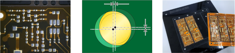
(Left) Position changes causing solder paste and pad shifts (Middle) Shape changes due to interference from solder mask and cover film (Right) Movement to the carrier board
The positional shifts of pads, solder paste, and components caused by the above reasons can lead to differences in the contact area between the component electrodes and the solder paste. The result is an imbalance of tension when the solder paste melts, pulling the component to one side, ultimately causing the angle of the component to shift or misalign.
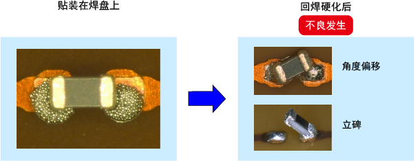
(Left) Position offset between solder paste and component (Right) Defects caused by uneven tension during melting
02
Suppressing Positional Shift Defects in Flexible Circuit Board Mounting!
TOP (Target On Paste) Mounting
By using the camera of the pick-and-place machine to identify the printed solder paste on the flexible circuit board and correcting the component mounting position, it is possible to mount the components at the center of the solder paste without being affected by pad position shifts and reference point deformations. Since the contact area of the solder paste with the component electrodes is uniform, the self-adjusting effect can be maximized, fixing the components in the expected position.
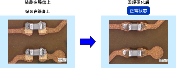
Through the self-adjusting effect, the components are moved to the correct position on the pads.
Since the self-adjusting function of TOP mounting works very well for small rectangular chip components below 1005, it is particularly suitable for the following types of circuit boards:・Circuit boards with a large number of small chips・Double-sided mounted circuit boards・Circuit boards using carrier boards By improving the mounting quality, unnecessary waste and rework hours can be reduced. ※ Depending on the state of the circuit board and the amount of positional shift, optimal results may not always be achievable.
TOP mounting is a complete module solution that confirms the printing position through the machine’s camera, thus not being affected by inconsistencies in image processing between machines. This means there is no need to introduce other machines, replace peripheral equipment, or modify machines, thereby reducing investment costs.
