Recently, I’ve been enjoying playing Need for Speed, so I bought a gaming steering wheel. After the delivery arrived, I couldn’t wait to unpack it. However, after playing for a while, I wanted to throw it away because the feel was really poor. The steering had no response when I slightly turned it, and when I turned it more, it suddenly jerked like it was on steroids. It was less enjoyable than using a keyboard. Throwing it in the trash seemed a bit wasteful, so I thought I could spend some effort to modify it and create a decent gaming controller. 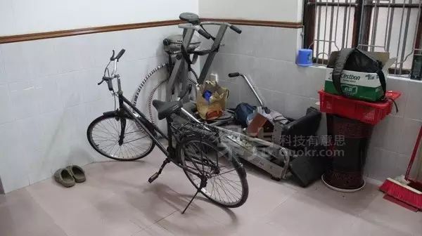 The only things at home that relate to “Fast and Furious” are a simple treadmill that has been unused for 10 years on the first floor and an old bicycle given by my neighbor. I chose the bicycle because I personally feel that raising the rear wheel of the bicycle makes it very natural to control. Another reason is that I can’t move the treadmill. The basic design is as follows:
-
Bicycle front ————> Racing steering wheel
-
Bicycle pedals ————> Racing accelerator
-
Bicycle left brake ————> Racing foot brake
-
Bicycle right brake ————> Racing handbrake or nitrous boost
2. Design Concept Generally, gaming steering wheels are equipped with linear potentiometers on the steering wheel and the accelerator brake. When players turn the steering wheel or press the accelerator brake, the resistance value of the potentiometer changes. By measuring the voltage change across the resistor through AD conversion, the change in the steering wheel or accelerator brake can be determined, and then it communicates with the computer via an MCU or USB chip. 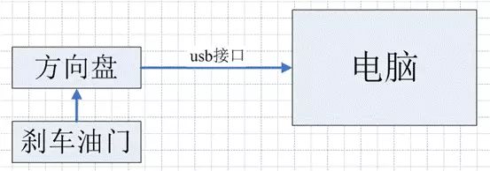 Since I don’t know much about USB communication, I directly used the main circuit board of the steering wheel for my project.
 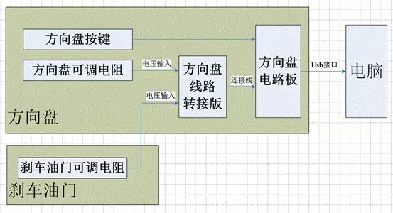 In simple terms, as long as I input a corresponding resistance to the main circuit board of the steering wheel, I can “trick” it into working and send corresponding data to the host computer (computer running Need for Speed). Our job is to use some sensors to measure certain parameters of the bicycle (speed, steering direction, whether braking), process them through an MCU, adjust the digital potentiometer, and connect it to the main circuit board of the steering wheel. Please see the detailed diagram:
 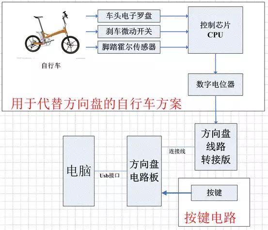 3. Tools One bicycle, one bicycle riding platform. Hall sensor module, micro switch, LPC2013 minimum system module, electronic compass module, accelerometer module, ULINK debugger, one computer, MDK keil4 development environment, multimeter, essential tools for electronics: soldering iron, solder wire, desoldering pump, a set of screwdrivers, tweezers, waterproof tape, bench drill, zip ties, etc. In short, all the necessary tools for soldering circuit boards should be available, so I won’t elaborate further. 4. Disassembling the Steering Wheel Disassemble the steering wheel and measure some parameters: the maximum resistance of the linear potentiometer of the steering wheel, the resistance when the steering wheel is fully turned left and right, and the resistance when the steering wheel is centered. The resistance when the brake is not pressed and the resistance when it is fully pressed. The resistance when the accelerator is not pressed and the resistance when it is fully pressed.
 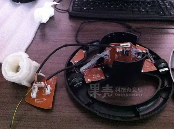 After measuring, I found that the brake and accelerator share a linear potentiometer.
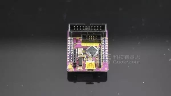
 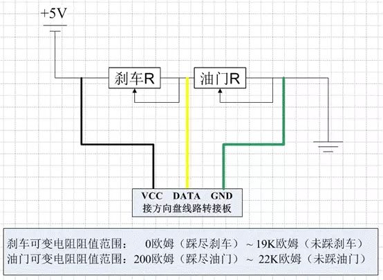 For the steering wheel, when it is centered, the resistance of the potentiometer is exactly half of the maximum resistance, so there is no need to pay too much attention to its resistance value. However, the selected potentiometer should not differ by more than one order of magnitude. 5. Circuit Design and Soldering 1. Since the ARM7 2103 module I bought already has a minimum system, all the pins are directly exposed, so I just need to extend the pins slightly and connect them to a socket for easy installation. The pins used in the entire MCU module include — SPI0 pins, I2C0 pins, two external interrupts, and some GPIO ports for indicator LEDs, push switches (optional), UART0 pins (for debugging output, optional), etc. There’s no need to provide the circuit diagram; if you understand the basics or have studied ARM, you should know how to connect them. I just sketched a rough diagram before starting the soldering, and the soldered board is as follows.
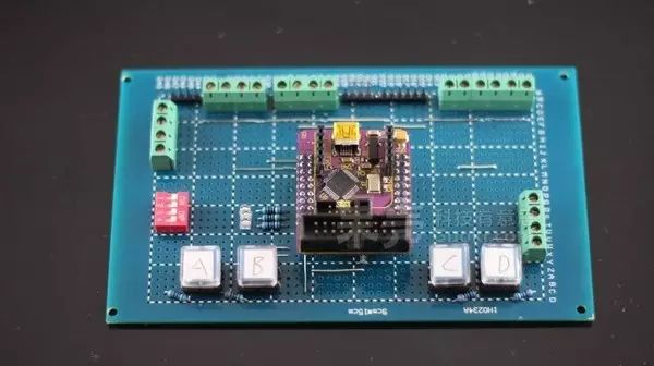
2. Take out the main circuit board of the steering wheel and the adapter board, solder them onto a universal board, and solder on the terminal block for easy installation. 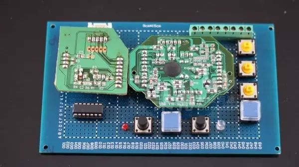 To facilitate installation, I also soldered a few circuit boards for two Hall sensors, the accelerometer, and the electronic compass, along with terminal blocks. Here’s a family photo.
 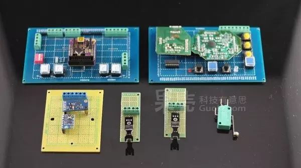 6. Module Detailed Introduction 1. Hall Sensor (measuring bicycle speed) The Hall sensor module works like this: it has three pins: VCC, GND, and DATA. In the default state, the DATA pin outputs a low level. If a magnet approaches, it generates a magnetic field cutting, and it will output a high level. When the magnet moves away from the sensor, it returns to low level. Therefore, a magnet is attached to the side of the bicycle pedal, and two Hall sensor modules are installed on either side of the pedal’s path. When pedaling, by calculating the time difference between the two Hall sensors, we can obtain the speed of the cyclist, which corresponds to the depth of the racing accelerator.
 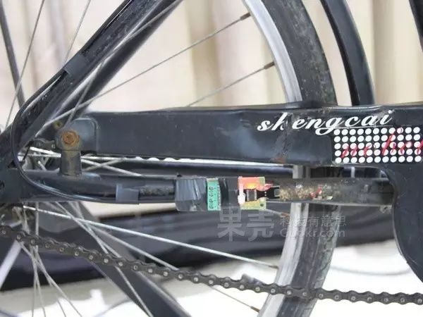 2. Electronic Compass and Accelerometer Module (measuring bicycle turning angle)
 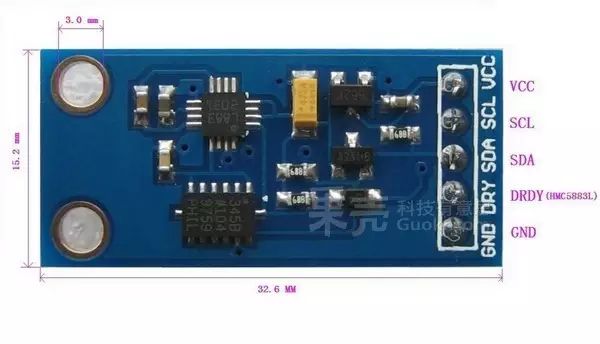 The electronic compass chip model I used is HMC5883L, with an I2C interface and a 75HZ data reading frequency. There’s not much to say; after powering up, it resets, and by setting the working parameters and mode via the I2C interface, data can be read. The data mode shows the components of the geomagnetic field along the XYZ axes, but I’m not entirely clear about it. The XYZ axes’ reference is related to the chip’s position. However, by extracting the data and calculating according to the chip manual, we can measure the angle with the geomagnetic field.
 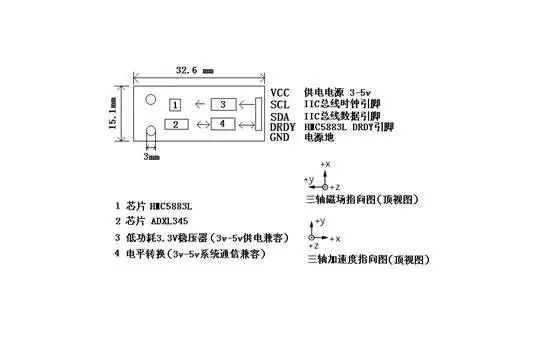 The module also includes an ADXL345 accelerometer, which also has an I2C interface. The main reason for using the accelerometer is that the bicycle’s front steering plane is not completely horizontal since the bicycle’s steering axis (not sure if that’s the right term) has an angle with the horizontal plane. This results in the entire module not functioning in a horizontal plane, meaning that the XY plane formed by the electronic compass is not parallel to the horizontal plane, and the Z-axis geomagnetic component is certainly not zero, at least not most of the time. That’s why the ADXL345 accelerometer is used to measure the tilt angle to correct the electronic compass data. In fact, I also bought another module that integrates an accelerometer and a gyroscope, originally to average out the errors of one accelerometer for calibration, but I didn’t use it. The downside is that because I used the electronic compass, every time I start playing, I need to calibrate it, as the bicycle’s position leads to inconsistent center orientations, so initialization is required. Even during play, if I get too excited and move the bicycle too much, I need to constantly recalibrate. The best solution would be to install a rotating potentiometer on the front instead of the electronic compass, but considering the installation of the potentiometer requires suitable gears and is cumbersome without molds, I gave up on that idea.
 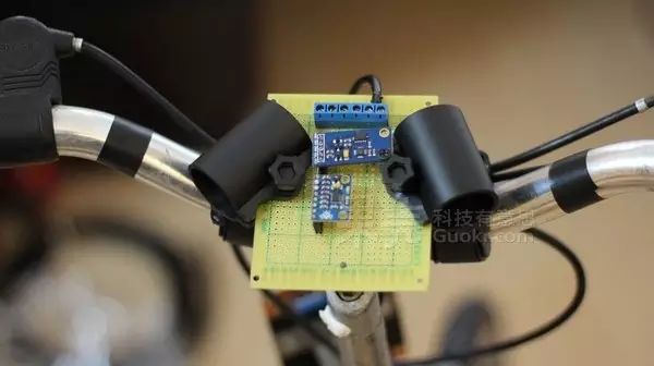 3. Micro Switch (brake, nitrous boost)
 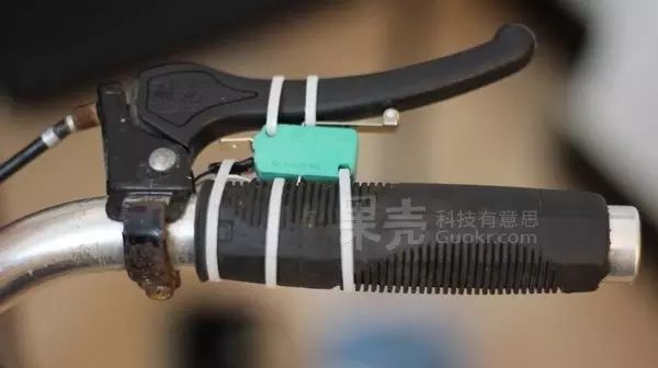 Two micro switches are installed on the bicycle brakes. The initial plan was to use pressure sensors, so the brake parameters would be analog, but the installation was too complicated, so I opted for a switch-based approach. The micro switches are directly connected to the steering wheel’s circuit board without going through the ARM7 LPC2103 circuit board. 4. Digital Potentiometer MCP42050.
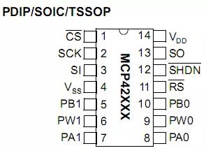
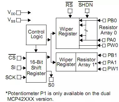
Maximum range 50K ohms, SPI communication interface, 2 potentiometers, with a precision of 50K ohm/256, which is more than sufficient. In the initial setting, the accelerator depth (i.e., speed) is divided into 10 levels, and the steering wheel is set to 5-degree intervals, making a total of 32 levels for left and right turns of 90 degrees each. This is more than enough. 5. LPC2103 module. Nothing much to say, used for data processing. 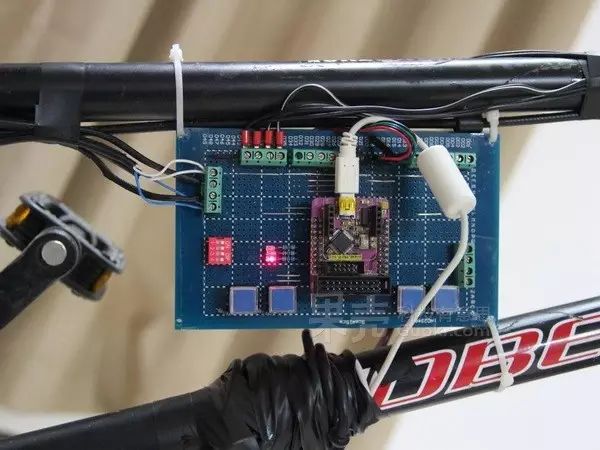 7. Programming and Debugging 1. I used a small operating system called Ucos, divided into four tasks. Task 1: Indicator light on and off. Task 2: Read data from the electronic compass and accelerometer, process the data to obtain the angle and write it into a global variable. Task 3: Process the data from the Hall sensor, writing the time interval (speed) into a global variable. Task 4: Based on the speed and steering angle from the two global variables, write the corresponding resistance value into the digital potentiometer.
 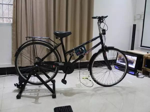 Author: bohua