A digital multimeter can be used to measure DC and AC voltage, DC and AC current, resistance, capacitance, frequency, batteries, diodes, and more. The overall circuit design is centered around a large-scale integrated dual-slope A/D converter, equipped with full-process overload protection circuits, making it a high-performance tool and an essential instrument for electricians.
1. Precautions Before Operation
(1) Set the ON-OFF switch to ON, check the 9V battery. If the battery voltage is insufficient,

or “BAT” will display on the screen, in which case, the battery should be replaced; if it does not appear, proceed with the following steps;
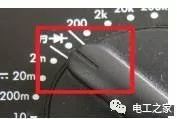
(2) Before testing, the function switch should be set to the desired range, and pay attention to the position of the pointer, as shown in the figure below:
(3) It is particularly important that during the measurement process, if you need to change the range or probe positions, you must remove both probes from the measurement object before changing the range or probe positions.
2. Using the Voltage Range and Precautions
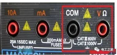
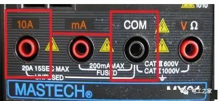
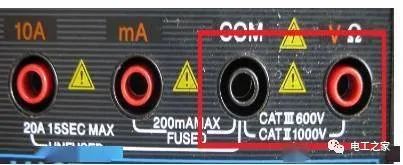
When measuring voltage, the black probe must be inserted into the COM hole, and the red probe into the V hole, as shown in the red box in the figure below;
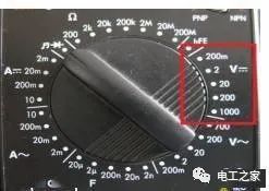
If measuring DC voltage, set the pointer to the DC range shown in the figure below:
If measuring AC voltage, set the pointer to the AC voltage range shown in the figure below:
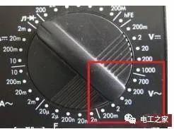
(1) If you do not know the voltage range to be measured, set the function switch to the maximum range and gradually lower the range (do not change the range during measurement);
(2) If “1” is displayed, it indicates an overload; the function switch should be set to a higher range;
(3) △! indicates not to input a voltage higher than the multimeter’s requirements; a higher voltage value may be displayed, but there is a risk of damaging the internal circuitry;
(4) When measuring high voltage, special care should be taken to avoid electric shock;
(5) The internal resistance of the digital multimeter’s voltage range is very high, at least in the megohm range, which has little effect on the measured circuit. However, the extremely high output impedance makes it susceptible to induced voltage, and in some electromagnetic interference environments, the data obtained may be false. It is important to avoid external magnetic fields affecting the multimeter (for example, when high-power electrical devices are in use);
(6) During the use of the multimeter, do not touch the metal part of the probes with your hands; this ensures measurement accuracy and personal safety.
3. Measuring Capacitance and Precautions
Method for measuring capacitance:
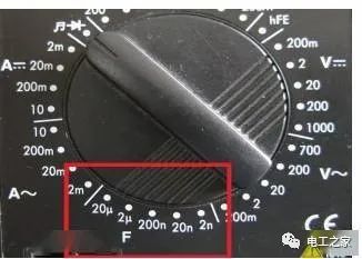
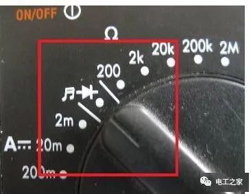
As shown in the box in the figure below, set the pointer to the capacitance range (F range).
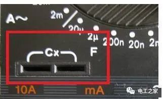
In the lower left corner of the digital multimeter’s range, there are two holes, labeled Cx, insert the capacitor component to be measured into them. If there is a polarized capacitor, pay attention to the positive and negative terminals.
Capacitance (or capacitance value) refers to the amount of charge stored under a given voltage; denoted as C, with the international unit being Farads (F), which characterizes the physical quantity of a capacitor’s ability to hold charge.
How to determine if a capacitor is good or bad?
Use an analog multimeter in ohm range (adjust the range according to the capacitance value), first discharge the capacitor, then touch the capacitor’s two terminals with the probes. The pointer will swing quickly and return to the starting position; if reversed, it will swing further and quickly return to the original position. If the pointer swings but does not return to the original position, the capacitor is leaking (it is normal for large electrolytic capacitors to have slight leakage). If the pointer does not move, the capacitor is open (if the capacitance is too small, such as a few pF, it may not be measurable; I can measure small capacitors like 3N3, 4N7 with a 10K range).
Method to check for capacitor leakage:
For capacitors above 1000 microfarads, first use the R×10Ω range for quick charging and preliminary estimation of capacitance, then switch to the R×1kΩ range to continue measuring. The pointer should not return but should stop at or very close to ∞; otherwise, there is leakage. For timing or oscillation capacitors below several tens of microfarads (such as oscillation capacitors in color TV switch power supplies), the leakage characteristics are very high; any leakage renders them unusable. In this case, after charging at R×1kΩ range, switch to R×10kΩ range for continued measurement, similarly, the pointer should stop at ∞ and not return.
4. Using the Current Range and Precautions
As shown in the box in the figure below, the multimeter’s current range is divided into AC and DC ranges; when measuring current, the multimeter pointer must be set to the corresponding range for measurement.
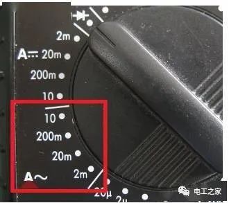
AC Range
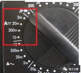
DC Range
When measuring current, if using the mA range, the black probe must be inserted into the COM hole, and the red probe into the mA hole, as shown in the box in the figure below;

If using the 10A range for measurement, the black probe remains in the COM hole, while the red probe is removed and inserted into the 10A hole, as shown in the box in the figure below.
Precautions for current measurement:
(1) If you do not know the current range to be measured, set the function switch to the maximum range and gradually lower the range (do not change the range during measurement);
(2) If the display only shows “1”, it indicates an overload; the function switch should be set to a higher range;
(3) The probe socket indicates that the maximum input current is 10A; measuring excessively high current will blow the fuse.
5. Using the Diode Range and Precautions
Set the multimeter pointer to the diode range shown in the box in the figure below, the black probe is inserted into the COM hole, and the red probe is inserted into the V hole. This range can not only measure diodes but also transistors, coding switches, and check circuit continuity.
Next, examples of transistors and potentiometers will be explained.
1. Structure of a Transistor:
The basic structure of a transistor is two reverse-connected PN junctions, which can be simply viewed as two connected diodes, as shown in the figure below, which can have PNP and NPN combinations.
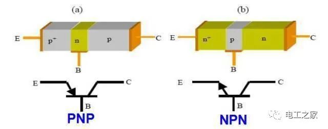
The three output terminals are called emitter (E), base (B), and collector (C) in order.
2. Measurement Method for Transistors:
Set the multimeter to the diode range. This range displays the voltage drop across the measured diode. To determine the type and polarity of the transistor, connect the probes to any two legs of the transistor; if the reading is around 700 (in millivolts), it indicates a silicon transistor. If the displayed value is around 200, it indicates a germanium transistor. If there is no display (open circuit shows 1), the red and black probes need to be swapped for testing. Additionally, the type of transistor can be determined: if the red probe is connected to one leg (base), and the other two legs are connected to the black probe and conduct (show a value), it indicates an NPN transistor. If the black probe is connected to one leg (base), and the other two legs are connected to the red probe and conduct (show a value), it indicates a PNP transistor. The identification of the emitter and collector requires other methods.
At the same time, using the resistance range, the transistor’s amplification factor and internal resistance can also determine whether the transistor is NPN or PNP.
3. Determining the Good or Bad Status of a Transistor:
Connect the probes to any two legs of the transistor; if there is no display (open circuit shows 1) or there is a beep, swap the red and black probes for testing. If the result is the same, the transistor can be determined to be faulty.
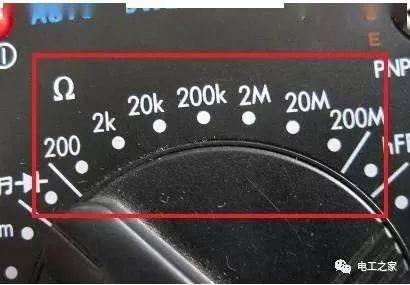
6. Using the Resistance Range and Precautions
Set the multimeter pointer to the resistance range shown in the box in the figure below, the black probe is inserted into the COM hole, and the red probe is inserted into the V hole, then measure the resistance value of the component.

Precautions for resistance measurement:
(1) If the measured resistance value exceeds the maximum value of the selected range, “1” will be displayed, and a higher range should be selected; for resistances greater than 1 MΩ or higher, it may take a few seconds for the reading to stabilize, which is normal for high resistance readings;
(2) When there is no input, such as in an open circuit, it will display “1”;
(3) When checking the internal circuit impedance, ensure that all power sources to the measured circuit are disconnected and all capacitors are discharged;
(4) When shorting 200MΩ, about four digits will be displayed; during measurement, this should be subtracted from the reading. For example, when measuring a 100MΩ resistor, if it shows 101.0, the fourth digit should be subtracted;
(5) The resistance range can be used to roughly detect the quality of a capacitor. Connect the red probe to the positive terminal of the capacitor and the black probe to the negative terminal. The multimeter’s reference power will charge the capacitor through the reference resistor; under normal conditions, the multimeter will show a charging voltage that gradually increases from a low value until it overflows. If it shows overflow “1” immediately upon charging, the capacitor is open; if it always shows a fixed resistance value or “000”, the capacitor is leaking or shorted;
(6) When checking circuit continuity, if there is no beep, it indicates that the circuit is open;
(7) When measuring small resistance values, short the two probes first, read the inherent resistance of the probe connection (generally 0.2 to 0.3 ohms) to correct the measured resistance value;
(8) The resistance range has over-voltage protection; mistakenly measuring voltage within the specified range will not cause damage. For example, the maximum allowable input voltage (DC or AC peak) for the resistance range of the DT-830 digital multimeter is 250 volts, which is the safety value for mistakenly using the resistance range to measure voltage. However, it is not allowed to measure resistance with live voltage (such as from batteries, human body, etc.), as this may lead to reduced accuracy or even damage to the multimeter.
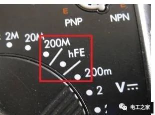
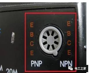
7. Using the hFE Range and Precautions
This range is mainly used to measure the amplification factor β of transistors. Before measuring, you must first determine whether the transistor is PNP or NPN type and confirm the polarity of each leg.
Other Precautions When Using a Multimeter:
(1) During the use of the multimeter, do not touch the metal parts of the probes with your hands; this ensures measurement accuracy and personal safety.
(2) When measuring a certain quantity, do not change the range while measuring, especially when measuring high voltage or large current; extra caution should be taken. Otherwise, the multimeter may be damaged. If a range change is needed, disconnect the probes first, then change the range before measuring.
Maintenance Precautions for Digital Multimeters:
A digital multimeter is a precision electronic instrument; do not change the circuits casually, and pay attention to the following points:
① Do not exceed the range during use;
② When the battery is not installed properly or the back cover is not tightened, do not use the multimeter;
③ Only replace the battery and fuse after the test probes are removed from the multimeter and the power is disconnected. For battery replacement: pay attention to the 9V battery usage; if replacement is needed, open the back cover screws and replace it with the same model battery. When replacing the fuse, please use the same model fuse;
④ After using the multimeter, set the range switch to “OFF”. If not used for a long time, also remove the internal battery to prevent battery corrosion of other components inside the multimeter.
Image and text sourced from the internet; if there is any infringement, please contact for deletion!