I2C (Inter-Integrated Circuit) communication bus is a key component in embedded system design. Its flexibility and high efficiency make it popular in advanced applications. This article aims to provide an in-depth analysis of the I2C communication bus, including its basic concepts, features, communication protocols, as well as advanced applications and best practices in different scenarios. The I2C interface uses only two signal lines, allowing multiple devices to be connected on the bus, with simple hardware implementation and strong scalability. The I2C communication protocol can be simulated using ordinary GPIO pins. The I2C interface is mainly used in applications where communication speed is not high and multiple devices need to communicate.
1. Basic Concepts of I2C Communication Bus
I2C is a multi-master, two-wire, low-speed serial communication bus widely used for communication between microcontrollers and various peripheral devices. It uses two lines: the Serial Data Line (SDA) and the Serial Clock Line (SCL) for bidirectional transmission.
Features
-
Two-wire Bus: I2C uses only two lines—the Serial Data Line (SDA) and the Serial Clock Line (SCL) for communication, effectively reducing connection complexity.
-
Multi-master and Multi-slave Support: I2C supports multiple master devices and multiple slave devices connected to the same bus. Each device has a unique address.
-
Variable Clock Rates: The I2C bus supports different rate modes, such as Standard Mode (100kbps), Fast Mode (400kbps), and High-Speed Mode (3.4Mbps).
-
Synchronous Communication: I2C is a synchronous communication protocol where data transmission is controlled by the clock signal (SCL).
-
Simple Connection: I2C communication has low hardware requirements, making it easy to connect between microcontrollers and peripheral devices.
-
Address Allocation: Each I2C device is identified by a 7-bit or 10-bit address, allowing multiple devices to be connected on the bus.
-
Blocking Transmission: I2C supports a blocking transmission mechanism, meaning the master device can control the bus during transmission to prevent other devices from sending data.
-
Wide Application: Due to its simplicity and flexibility, I2C is widely used in various electronic products such as sensors, LCD displays, EEPROMs, etc.
-
Bus Arbitration and Collision Detection: In multi-master mode, I2C can handle situations where multiple master devices attempt to control the bus simultaneously.
-
Low Power Consumption: The design of the I2C bus makes it a low-power communication method suitable for battery-powered devices.
Basic Characteristics
-
Bus Structure:
-
Two-wire: Communication is done using two lines, namely the Serial Data Line (SDA) and the Serial Clock Line (SCL).
-
Multi-master and Multi-slave Structure: Supports multiple master and multiple slave devices connected to the same bus.
-
Communication Method:
-
Synchronous Serial: Data transmission is synchronized to the clock signal.
-
Byte Format: Each byte consists of 8 bits of data, along with start and stop conditions and an optional acknowledgment bit.
-
Clock Rate:
-
Supports various rates, including Standard Mode (100kbps), Fast Mode (400kbps), and High-Speed Mode (3.4Mbps).
Working Principle
-
Bus Control:
-
Start and Stop Conditions: Communication is initiated and terminated by the master device generating specific signal patterns on the SDA line.
-
Address Frame: Each time communication starts, the master device sends an address frame to specify the slave device to communicate with.
-
Data Transmission:
-
Master-slave Communication: The master device controls the clock signal to send or receive data from the slave device.
-
Acknowledgment Bit: After each byte, the receiver sends an acknowledgment bit (ACK) or a non-acknowledgment bit (NACK) to inform the sender whether the data was successfully received.
Address and Arbitration
-
Device Address:
-
7-bit or 10-bit Address: Each I2C device has a unique address, allowing multiple devices to be connected on the same bus.
-
Bus Arbitration:
-
In multi-master mode, when two master devices attempt to control the bus simultaneously, the I2C protocol includes an arbitration mechanism to determine which device gains control.
2. I2C Data Transmission Process
In I2C communication, the master sends clock signals through the clock line SCL and sends data (including slave address, commands, data packets, etc.) through the data line SDA. After sending a frame of data, it must wait for the slave’s response before continuing to send the next frame, thus I2C is a synchronous communication.
In I2C communication, data is transmitted on one data line SDA, and at any given time, the data transmission direction can only be unidirectional, either from A to B or from B to A; bidirectional communication is achieved by switching the transmission direction, thus I2C is half-duplex communication.
Data Format
The data packet size in I2C communication is 8 bits, mainly consisting of three types—commands, byte addresses, and data. During data transmission, the order is high bit first, low bit last (i.e., MSB First, LSB Last).

I2C communication determines several communication states through the clock line SCL and the data line SDA—Idle State, Start Signal, Stop Signal, Data Bit Transmission, Acknowledgment Signal.
The Idle State occurs when both SDA and SCL lines are high, indicating that the bus is idle. At this time, all device output MOSFETs are in cutoff state, releasing the bus, with the pull-up resistors on both signal lines pulling the level high.
The Start Signal is defined as the falling edge on the SDA line while the SCL line remains high, marking the beginning of a data transmission. The Start Signal is established by the master, and the I2C bus must be in the idle state before establishing this signal.
The Stop Signal is defined as the rising edge on the SDA line while the SCL line remains high, marking the termination of a data transmission. The Stop Signal is established by the master, and after establishing this signal, the I2C bus will return to the idle state.
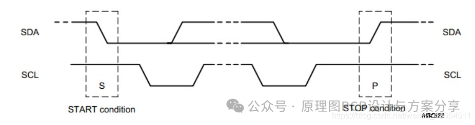
Data Bit Transmission in I2C communication corresponds each clock on the SCL line to a data bit on the SDA line. During data transmission, the level on SDA must remain stable while SCL is high, with low level representing data 0 and high level representing data 1. The level on SDA can only change state during the low level of SCL.
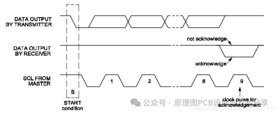
The Acknowledgment Signal indicates that all data on the I2C bus is transmitted as 8-bit bytes. After the sender sends a byte, it releases the data line at the start of the 9th clock, with the receiver providing an acknowledgment signal. A low level acknowledgment signal (ACK) indicates that the receiver has successfully received the byte; a high level non-acknowledgment signal (NACK) generally indicates that the receiver did not successfully receive the byte. The requirement for providing a valid acknowledgment signal (ACK) is that the receiver must pull the SDA line low during the low level period before the 9th clock pulse and ensure that it remains stable low during the high level of that clock. If the receiver is the master, it sends a NACK signal after receiving the last byte to inform the sender to stop sending data and release the SDA line so that the master can send a stop signal.
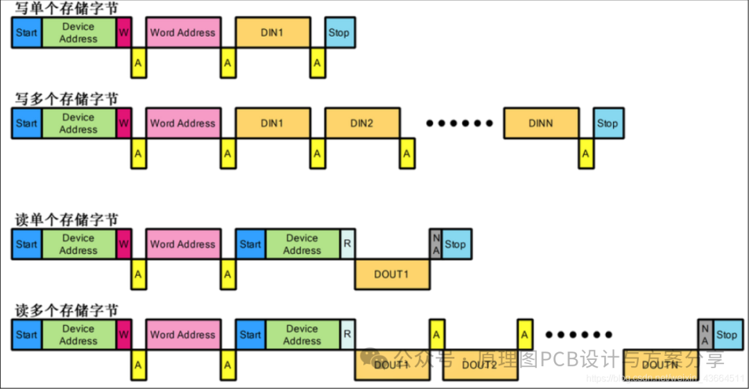
The specific communication process is illustrated by the example of writing a single storage byte:
Initial State: Both SCL and SDA are high, and the bus is in an idle state;
→ Start Signal: When SCL is high, SDA transitions from high to low, generating a falling edge, marking the start of I2C communication;
→ Send 7-bit Slave Address and 1-bit Read/Write Command: Data is transmitted bit by bit, following the order of high bit first and low bit last, adhering to the principle that the data on SDA remains unchanged while SCL is high and changes while SCL is low, sending one bit of address data per clock pulse;
→ Receive Response: In I2C communication, after sending 8 bits of data, a 1-bit response is received; at this time, the master releases the data line SDA, and reads the acknowledgment signal on SDA during the high level of the 9th clock, where 0 represents ACK and 1 represents NACK; only upon receiving the ACK signal can the subsequent operation continue, otherwise the communication process is restarted;
→ Send 8-bit Byte Address: Same as above;
→ Receive Response: Same as above;
→ Write 8-bit Data: Same as above;
→ Receive Response: Same as above;
→ Stop Signal: When SCL is high, SDA transitions from low to high, generating a rising edge, marking the end of I2C communication.
Disclaimer:
This account maintains neutrality regarding the statements and views of all original and reprinted articles. The articles are provided solely for readers’ learning and exchange. Copyright for articles, images, etc., belongs to the original authors. If there is any infringement, please contact for deletion.