Skip to content
Continuing from the previous article on Introduction to MMU in ARMV8-A – Part 2.
This article will continue from the last section and explain the multi-level page tables of MMU. The previous section discussed an example of a single-level page table, while this section will discuss an example of a two-level page table.
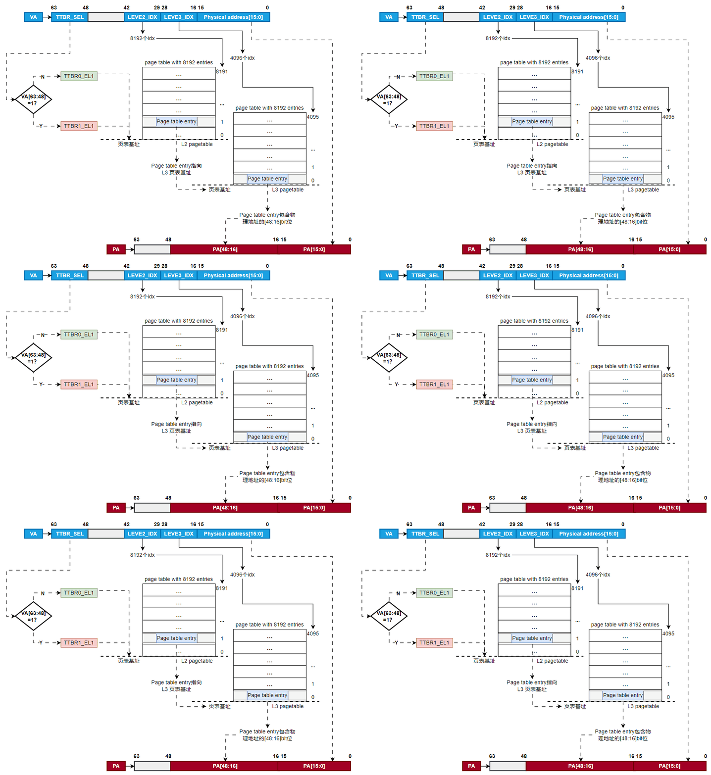
Below is an example of a 64K page size, where the MMU will establish an instance of a two-level page table. In this example, the MMU needs to perform two page table lookups: the first-level page table holds the address of the second-level page table, and the second-level page table holds the target physical address. There can be multiple different first-level page tables pointing to the same second-level page table. What does this mean? It means that different virtual addresses of the same process can point to the same physical address.
In this example, we still assume that the MMU can address a maximum of 42-bit address space, and the page size is 64KB.
Note: The 42-bit address space mentioned here does not mean that the value of the virtual address cannot exceed 42 bits, but rather that based on a certain address as a base, it can continue to address a memory space of 42 bits in size. Our virtual address value can still use a 64-bit value.
Next, let’s see how the MMU looks up the physical address based on the virtual address when there are two levels of page tables.
Step 1: If the virtual address VA[63:42] = all 1s, the MMU will select TTBR1_EL1 as the page table base address; if the virtual address VA[63:42] = all 0s, the MMU will select TTBR0_EL1 as the page table base address;
Step 2: The page table base address contains 8192 x 64-bit page table entry items. These 8192 entries are indexed using VA[41:29]. The MMU then reads the corresponding next-level translation table entry from the table.
Step 3: The MMU checks the validity of the translation table entry and determines whether the requested virtual address has the correct access permissions. If the check passes, it can access that memory address.
Step 4: The MMU finds the base address of the second-level page table based on the entry from the first-level page table. Then, it uses the virtual address’s [28:16] for the second index lookup, which has 4096 entries. As shown in Figure 5:
Step 5: The bits [47:29] are transferred from the level 2 translation table entry to form the base address of the level 3 translation table.
Step 6: The bits [28:16] are used to index the level 3 translation table entries. The MMU reads the level 3 translation table entry.
Step 7: After the MMU reads the entry, it checks whether the entry is valid and whether the requested memory access is allowed.
Step 8: In Figure 5, the level 3 translation table entry is associated with a 64KB page, occupying bits [15:0]. The bits [47:16] are taken from the level 3 entry for the PA’s [47:16] bit value content.
Step 9: Since the page size is 64KB, the bits [15:0] of the VA will be directly used for the PA’s [15:0].
Step 10: Finally, the MMU will find the address information of PA’s [47:0] and return it.
Similarly, if the page table has more levels, the MMU will break down the addressing according to the page size, looking up entries level by level until it finds the physical page.
Secure and Non-Secure Addresses
The ARM architecture defines two address spaces: secure address space and non-secure address space. Theoretically, these two address spaces are independent and do not interfere with each other. A system can be designed to have two address spaces. However, in most cases, a real system treats the secure address space and non-secure address space as two different attributes for controlling access permissions. For example, the normal world can only access the non-secure address space, while the secure world can access both. This functional scenario requires that the MMU is enabled. Because addressing will always allow the MMU to access through the page table, thus leveraging the MMU to achieve the functions of secure and non-secure address spaces.
We welcome everyone to continue reading the next article “Introduction to MMU in ARMV8-A – Part 4”.