Description: This article explains the application of MODBUS. Currently, the communication protocol between industrial control upper and lower machines predominantly uses MODBUS, highlighting the importance of machine-to-machine communication.
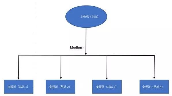
1. MODBUS System Framework Diagram
2. Application of MODBUS
The underlying communication of MODBUS uses RS485 signals connected via twisted pairs, allowing for long transmission distances of up to 1000 meters, good anti-interference performance, and low cost, making it widely used in industrial control device communications. Many manufacturers’ frequency converters and controllers now adopt this protocol.
The data transmission formats include HEX code data and ASCII code, referred to as MODBUS-RTU and MODBUS-ASCII protocols, respectively. The former transmits data directly, while the latter requires conversion to ASCII code before transmission. Therefore, the MODBUS-RTU protocol has higher communication efficiency, is simpler to process, and is more commonly used.
MODBUS operates in a master-slave communication mode, using a master query and slave response method. Each communication is initiated by the master station, with the slave station responding passively. Therefore, controlled devices like frequency converters generally have a slave protocol built-in, while control devices like PLCs need to have both master and slave protocols.
Taking the MODBUS-RTU protocol as an example, the typical format of the communication frame is as follows: Request frame format: Slave address + 0x03 + Register starting address + Number of registers + CRC check.
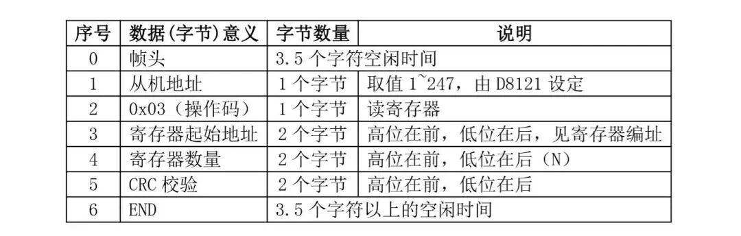
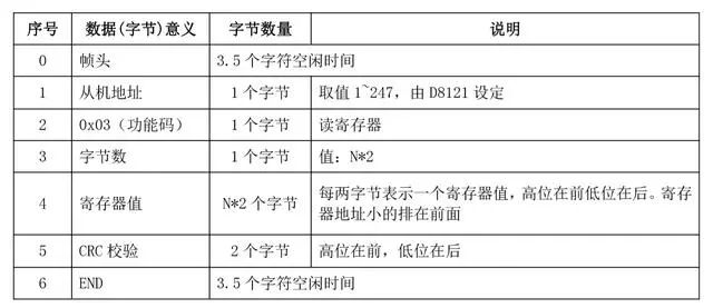
Normal response frame format: Slave address + 0x03 + Byte count + Register values + CRC check
3. Important Information to Note When Programming PLCs:
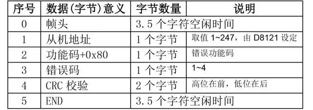
Slave address: In the master station’s sent frame, this address indicates the target receiving slave’s address; in the slave response frame, it indicates the local address. The range for slave address settings is 1 to 247, with 0 being the broadcast communication address.
Operation type: Indicates read or write operations; 0x1 = read coil operation; 0x03 = read register operation; 0x05 = write coil operation; 0x06 = write register operation.
For frequency converters, only 0x03 read and 0x06 write operations are supported. Register starting address: Indicates the register address to be accessed in the slave; for MD280 and MD320 series frequency converters, this corresponds to the “function code number”, “command address”, and “operating parameter address”; Number of data: The number of consecutive data points to be accessed starting from the “register starting address”, measured in words for register variables.
Register parameters (data): The data to be rewritten (host rewrite) or the data to be read (slave response);
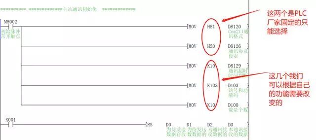
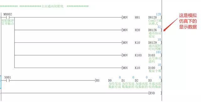
4. Program Writing and Explanation