Modbus Communication Protocol
1. Overview
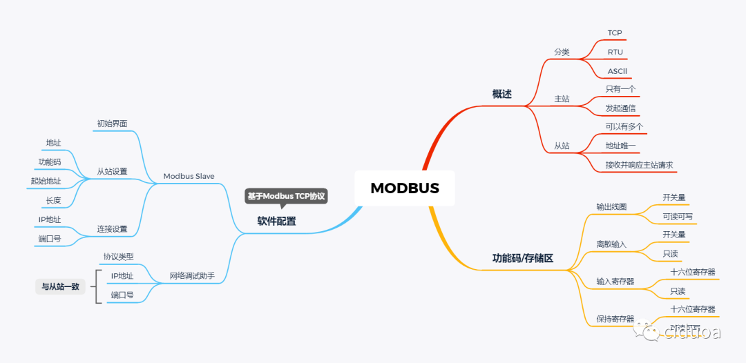
The Modbus communication protocol is an industrial field bus protocol standard. The commonly used Modbus protocols include three types: Modbus TCP, Modbus RTU, and Modbus ASCII.
The Modbus communication protocol addresses the issue of sending information between electronic devices over serial lines. This protocol implements a master/slave model within its architecture. The Modbus master station (Master) is responsible for requesting information from other devices (Slave). There is only one Modbus master station in a standard Modbus network.
2. Differences Between Master and Slave
The master (Master) is the device that initiates Modbus communication. It controls the communication process, sends requests to the slave, and processes the response data returned by the slave. The master can connect to multiple slaves simultaneously, but each slave must have a unique address.
The slave (Slave) is the device that receives and responds to requests from the master. The slave will only respond when the master sends a request; it cannot initiate communication on its own. The address of the slave is used to uniquely identify its location in the communication network.
3. Modbus Function Codes and Storage Areas
1) Function Codes

2) Storage Areas
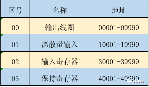
Output Coils: The operation unit is a 1-bit switch quantity, the output bit of the PLC, which can be read and written in Modbus.
Discrete Input: The operation unit is a 1-bit switch quantity, the input bit of the PLC, which is read-only in Modbus.
Input Registers: The operation unit is a 16-bit word (two bytes) data, registers that can only be changed from the analog input end in the PLC, which are read-only in Modbus.
Holding Registers: The operation unit is a 16-bit word (two bytes) data, registers used for outputting analog signals in the PLC, which can be read and written in Modbus.
Software Configuration
(Taking Modbus TCP Communication Protocol as an Example)
1. Required Software
Network Debugging AssistantModbus Slave
2. Configuring the Network Debugging Assistant
Configure the Network Debugging Assistant according to the diagram below
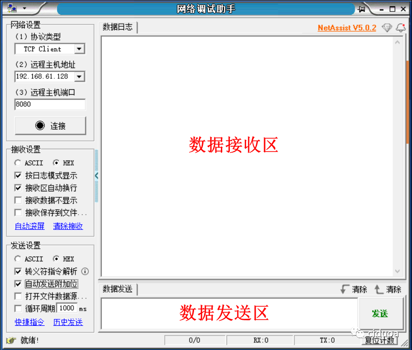
Protocol Type: TCP Client
Remote Host Address: Must be consistent with the computer’s IP address
Remote Host Port: Can be set arbitrarily, set to 8080 here
3. Configuring Modbus Slave
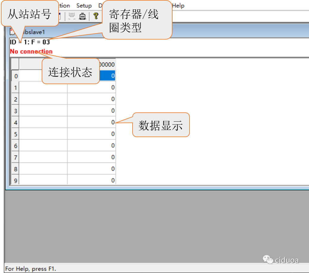
1) Initial Interface
This interface can display the slave address, register/coil type, current data, and other contents.
2) Connection Settings
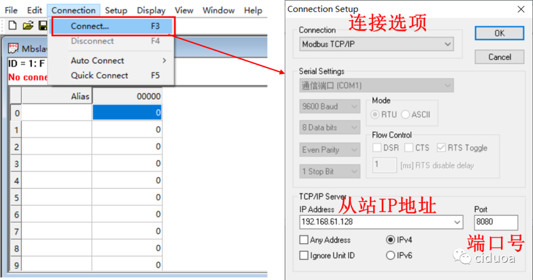
Click on the menu bar “Connection” —— “Connect…” to pop up the connection configuration window.
3) Slave Settings
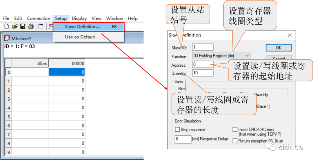
Click on the menu bar “Setup” —— “Slave Definition…” to open the slave settings interface.
(Reply with “Software” to get the corresponding software link)
(Do any of you have a group chat for Mitsubishi? Can you add me in?)
Your suggestions are my motivation to move forward

WeChat:
2960536263