

Modbus Communication Protocol
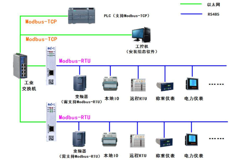
Introduction: The ModBus network is an industrial communication system formed by connecting programmable controllers with intelligent terminals and computers via public or local dedicated lines. Its system structure includes both hardware and software. It can be applied to various data acquisition and process monitoring.
The ModBus network has only one master, and all communication is initiated by it. The network can support as many as 247 remote slave controllers, but the actual number of supported slaves depends on the communication equipment used. By using this system, each PC can exchange information with the central master without affecting its own control tasks.
Understanding the Modbus communication protocol allows you to use various third-party software for communication testing on-site.
The Modbus protocol includes ASCII, RTU, TCP, etc., but does not specify the physical layer. This protocol defines the message structure that controllers can recognize and use, regardless of the network used for communication. Standard Modicon controllers use RS232C to implement serial Modbus. The ASCII and RTU protocols of Modbus specify the structure of messages, data, commands, and responses. Data communication uses a Master/Slave method, where the Master sends a data request message, and upon receiving a correct message, the Slave can send data back to the Master in response to the request; the Master can also directly send messages to modify Slave data, achieving two-way read/write.
The Modbus protocol requires data verification. In serial protocols, in addition to parity checks, the ASCII mode uses LRC checks, and the RTU mode uses 16-bit CRC checks, but the TCP mode does not have additional verification requirements since the TCP protocol is a connection-oriented reliable protocol. Additionally, Modbus uses a Master/Slave method to periodically send and receive data. In practical use, if a Slave site disconnects (due to failure or shutdown), the Master can diagnose it, and when the failure is repaired, the network can automatically reconnect. Therefore, the reliability of the Modbus protocol is relatively good.
For the Modbus ASCII, RTU, and TCP protocols, TCP and RTU protocols are very similar. We just need to remove the two-byte checksum from the RTU protocol, then add five 0s and a 6 at the beginning of the RTU protocol and send it through the TCP/IP network protocol.
1. Communication Transmission Method:
Communication transmission is divided into an independent header and encoded data sent. The following communication transmission method definitions are also compatible with the ModBus RTU communication specification:
Initial structure = ≥4 bytes of time
Address code = 1 byte
Function code = 1 byte
Data area = N bytes
Error check = 16-bit CRC code
End structure = ≥4 bytes of time
Address code: The address code is the first byte of the communication transmission. This byte indicates which slave with the user-defined address code will receive the information sent by the master. Each slave has a unique address code, and all response messages start with their respective address codes. The address code sent by the master indicates the address of the slave to which the message will be sent, while the address code sent by the slave indicates the address of the slave that is responding.
Function code: The second byte of the communication transmission. The ModBus communication specification defines function codes ranging from 1 to 127. This instrument only utilizes a portion of these function codes. As a master request to send, the function code tells the slave what action to perform. As a slave response, the function code sent by the slave is the same as that sent by the master, indicating that the slave has responded to the master’s operation. If the highest bit of the function code sent by the slave is 1 (for example, function code greater than 127), it indicates that the slave did not respond to the operation or an error occurred.
Data area: The data area varies according to different function codes. The data area can be actual values, set points, addresses sent from the master to the slave, or addresses sent from the slave to the master.
CRC code: A two-byte error detection code.
2. Communication Protocol:
When the communication command is sent to the instrument, the device with the corresponding address code receives the communication command, removes the address code, reads the information, and if there is no error, executes the corresponding task; then sends the execution result back to the sender. The returned information includes the address code, the function code of the action performed, the data of the result after the action, and the error check code. If there is an error, no information is sent.
1. Information Frame Structure
Address code Function code Data area Error check code
8 bits 8 bits N × 8 bits 16 bits
Address code: The address code is the first byte (8 bits) of the information frame, ranging from 0 to 255. This byte indicates which user-set address slave will receive the information sent by the master. Each slave must have a unique address code, and only slaves matching the address code can respond. When a slave returns information, the corresponding address code indicates where the information came from.
Function code: The function code sent by the master tells the slave what task to perform. The function codes listed in Table 1-1 have specific meanings and operations.
Data area: The data area contains what action needs to be executed by the slave or the returned information collected by the slave. This information can be values, reference addresses, etc. For example, if the function code tells the slave to read the value of a register, the data area must include the starting address of the register to be read and the read length. The address and data information vary for different slaves.
Error check code: The master or slave can use the check code to determine whether the received information has errors. Sometimes, due to electronic noise or other interferences, information may undergo slight changes during transmission, and the error check code ensures that the master or slave does not act on erroneous information during transmission. This increases the safety and efficiency of the system. Error checking uses the CRC-16 method.
Note: The format of the information frame is basically the same: address code, function code, data area, and error check code.
2. Error Checking
The Redundant Cyclic Code (CRC) contains 2 bytes, or 16 bits. The CRC code is calculated by the sending device and placed at the end of the sent information. The receiving device recalculates the CRC code of the received information and compares it with the received CRC code. If they do not match, it indicates an error.
3. Function Codes Supported by Modbus:
|
|
|
|
|
|
|
|
|
|
|
|
|
|
|
|
|
|
|
|
|
|
|
|
|
|
|
|
|
|
|
|
|
|
|
|
|
|
|
|
|
|
|
|
|
|
|
|
|
|
|
|
|
|
|
|
|
|
|
|
|
|
|
|
|
|
|
|
|
|
|
|
|
|
|
|
|
|
|
|
|
|
|
|
|
|
|
|
|
|
|
|
|
|
|
|
|
|
|
|
|
|
|
|
|
|
|
|
4. Detailed Explanation of Function Code Commands:
Among these function codes, the most commonly used are function codes 1, 2, 3, 4, 5, and 6, which can be used to perform read and write operations on digital and analog values of the lower machine.
1. Command 01, Read Writable Digital Registers (Coil Status):
The computer sends the command: [Device Address] [Command Number 01] [Starting Register Address High 8 Bits] [Low 8 Bits] [Number of Registers to Read High 8 Bits] [Low 8 Bits] [CRC Check Low 8 Bits] [CRC Check High 8 Bits]
Example: [11][01][00][13][00][25][CRC Low][CRC High]
Meaning as follows:
<1>Device Address: Multiple devices can be connected on a 485 bus, and the device address here indicates which device to communicate with. In the example, it is meant to communicate with device 17 (decimal 17 is hexadecimal 11).
<2>Command Number 01: The command number for reading digital values is fixed at 01.
<3>Starting Address High 8 Bits, Low 8 Bits: Indicates the starting address of the switch quantity to be read (the starting address is 0). For example, in the example, the starting address is 19.
<4>Number of Registers High 8 Bits, Low 8 Bits: Indicates how many switch quantities to read from the starting address. In the example, it is 37 switch quantities.
<5>CRC Check: Check from the beginning up to this point.
The device responds: [Device Address] [Command Number 01] [Returned Byte Count] [Data1][Data2]…[DataN] [CRC Check High 8 Bits] [CRC Check Low 8 Bits]
Example: [11][01][05][CD][6B][B2][0E][1B] [CRC High] [CRC Low]
Meaning as follows:
<1>Device Address and Command Number are the same as above.
<2>Returned Byte Count: Indicates the number of data bytes, which is the value of n in Data1, 2…n.
<3>Data1…n: Each data is an 8-bit number, so each data represents the value of 8 switch quantities, where each bit being 0 indicates the corresponding switch is off, and 1 indicates it is on. For example, in the example, it indicates that switch 20 (index 19) is on, switch 21 is off, switch 22 is on, switch 23 is on, switch 24 is off, switch 25 is off, switch 26 is on, switch 27 is on… If the number of switch quantities queried is not a multiple of 8, then the high part of the last byte is meaningless and set to 0.
<4>CRC check is the same as above.
2. Command 05, Write Digital Value (Coil Status):
The computer sends the command: [Device Address] [Command Number 05] [Register Address to be Set High 8 Bits] [Low 8 Bits] [Data to be Set High 8 Bits] [Low 8 Bits] [CRC Check Low 8 Bits] [CRC Check High 8 Bits]
Example: [11][05][00][AC][FF][00][CRC High][CRC Low]
Meaning as follows:
<1>Device Address is the same as above.
<2>Command Number: The command number for writing digital values is fixed at 05.
<3>Register Address to be Set High 8 Bits, Low 8 Bits: Indicates the address of the switch to be set.
<4>Data to be Set High 8 Bits, Low 8 Bits: Indicates the state of the switch quantity to be set. In the example, it is to close the switch. Note that only [FF][00] indicates closed and [00][00] indicates open; other values are illegal.
<5>Note that this command can only set one switch quantity state at a time.
The device responds: If successful, it returns the command sent by the computer as is; otherwise, it does not respond.
3. Command 03, Read Writable Analog Registers (Holding Registers):
The computer sends the command: [Device Address] [Command Number 03] [Starting Register Address High 8 Bits] [Low 8 Bits] [Number of Registers to Read High 8 Bits] [Low 8 Bits] [CRC Check High 8 Bits] [CRC Check Low 8 Bits]
Example: [11][03][00][6B][00][03] [CRC High][CRC Low]
Meaning as follows:
<1>Device Address is the same as above.
<2>Command Number: The command number for reading analog values is fixed at 03.
<3>Starting Address High 8 Bits, Low 8 Bits: Indicates the starting address of the analog value to be read (the starting address is 0). For example, the starting address in the example is 107.
<4>Number of Registers High 8 Bits, Low 8 Bits: Indicates how many analog values to read from the starting address. In the example, it is 3 analog values. Note that in the returned information, one analog value requires two bytes to return.
The device responds: [Device Address] [Command Number 03] [Returned Byte Count] [Data1][Data2]…[DataN] [CRC Check High 8 Bits] [CRC Check Low 8 Bits]
Example: [11][03][06][02][2B][00][00][00][64] [CRC High] [CRC Low]
Meaning as follows:
<1>Device Address and Command Number are the same as above.
<2>Returned Byte Count: Indicates the number of data bytes, which is the value of n in Data1, 2…n. In the example, it returns 3 analog values, because one analog value requires 2 bytes, so a total of 6 bytes.
<3>Data1…n: Where [Data1][Data2] are the high and low 8 bits of the first analog value, [Data3][Data4] are the high and low 8 bits of the second analog value, and so on. The returned values in the example are 555, 0, and 100.
<4>CRC check is the same as above.
4. Command 06, Write Single Analog Register (Holding Register):
The computer sends the command: [Device Address] [Command Number 06] [Register Address to be Set High 8 Bits] [Low 8 Bits] [Data to be Set High 8 Bits] [Low 8 Bits] [CRC Check High 8 Bits] [CRC Check Low 8 Bits]
Example: [11][06][00][01][00][03] [CRC High] [CRC Low]
Meaning as follows:
<1>Device Address is the same as above.
<2>Command Number: The command number for writing analog values is fixed at 06.
<3>Register Address to be Set High 8 Bits, Low 8 Bits: Indicates the address of the analog register to be set.
<4>Data to be Set High 8 Bits, Low 8 Bits: Indicates the analog value to be set. For example, in the example, the value of register 1 is set to 3.
<5>Note that this command can only set one analog value state at a time.
The device responds: If successful, it returns the command sent by the computer as is; otherwise, it does not respond.
5. Command 16, Write Multiple Analog Registers (Holding Registers):
The computer sends the command: [Device Address] [Command Number 16] [Register Address to be Set High 8 Bits] [Low 8 Bits] [Data Count High 8 Bits] [Data Count Low 8 Bits] [Data to be Set High 8 Bits] [Low 8 Bits][……][……] [CRC Check High 8 Bits] [CRC Check Low 8 Bits]
Example: [11][16][00][01][00][01][00][05] [CRC High] [CRC Low]
Meaning as follows:
<1>Device Address is the same as above.
<2>Command Number: The command number for writing analog values is fixed at 16.
<3>Register Address to be Set High 8 Bits, Low 8 Bits: Indicates the address of the analog register to be set.
<4>Data Count High 8 Bits, Low 8 Bits: Indicates the number of data to be set, here it is 1.
<5>Data to be Set High 8 Bits, Low 8 Bits: Indicates the analog value to be set. For example, in the example, the value of register 1 is set to 5.
The device responds: If successful, it returns the command sent by the computer as is; otherwise, it does not respond.
The device responds: [Device Address] [Command Number 16] [Register Address to be Set High 8 Bits] [Low 8 Bits] [Data Count High 8 Bits] [Data Count Low 8 Bits] [CRC Check High 8 Bits] [CRC Check Low 8 Bits], as shown in the above example:
[11][16][00][01][00][01] [CRC High] [CRC Low]