


A weight instrument supporting the Modbus protocol
You can adjust according to your requirements, as long as it is consistent with the PLC side.
Baud rate: 9600
Data format: 8n1: 8 data bits / no parity bit
Communication method: Modbus protocol
Checksum: OFF
Instrument communication address: 1
Here we only need to read the current real-time weight of the instrument.

The address for the instrument’s real-time weight is 0, corresponding to 40001 in Modbus communication.
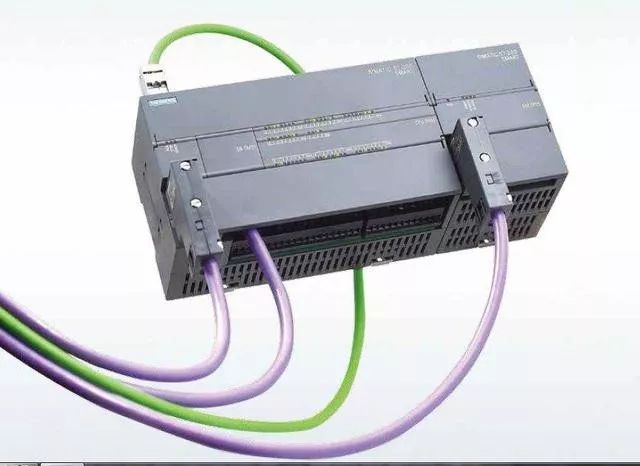
200smartPLC
Connect the RS485 interface A, B of the instrument to the DB9 interface of the PLC (DB9 interface 3 is A, 8 is B).
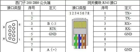
I remember that 3 is A, 8 is B. I don’t know why this image shows otherwise, but it doesn’t matter. If different, just swap the two wires.
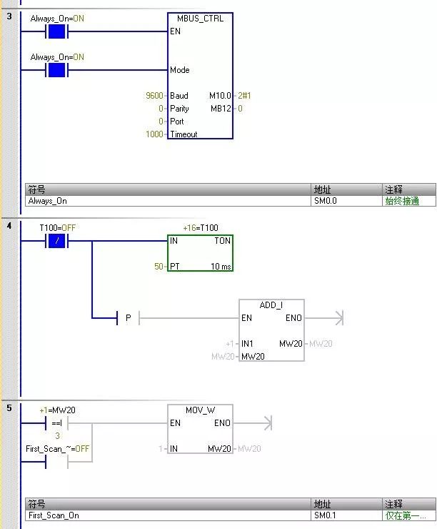
Preparation is complete, now let’s start our PLC programming. Because the 200smart software already includes the Modbus protocol library, we don’t need to add it separately. Below is how to program.
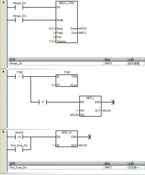
The value entered for “Mode” is used to select the communication protocol. When the input value is 1, the CPU port is assigned to the Modbus protocol and this protocol is enabled.
The parameter “Parity” should be set to match the parity of the Modbus slave device. 0 (no parity).
The parameter “Port” sets the physical communication port (0 = integrated RS-485 in CPU).
The parameter “Timeout” is set to the number of milliseconds to wait for the slave to respond. A typical value is 1000 ms (1 s).
When the MBUS_CTRL command completes, it returns “TRUE” to the “Done” output.
The “Error” output contains the result of the command execution.
The above parameter settings correspond to those on the weight instrument.
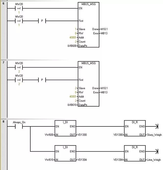
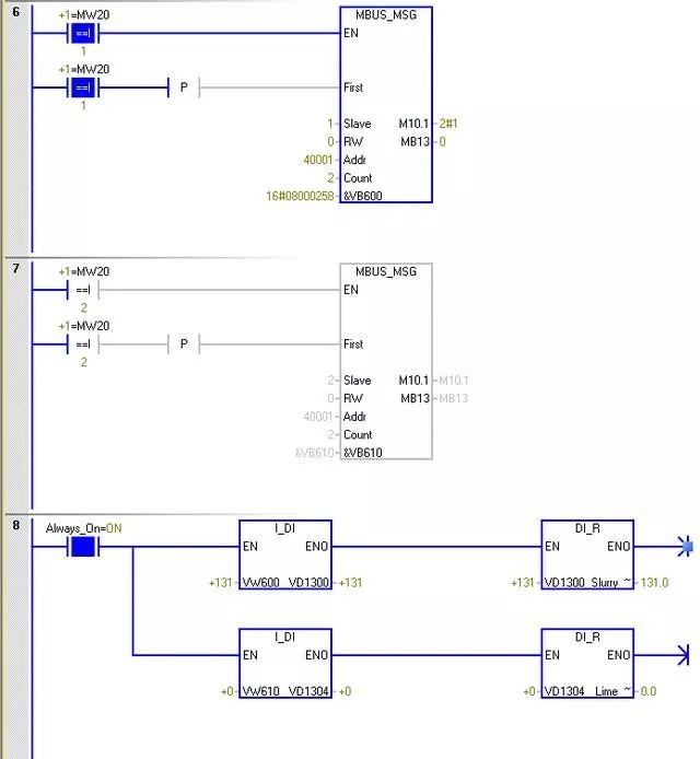
The parameter “Slave” is the address of the Modbus slave device. The allowed range is 0 to 247. Address 0 is the broadcast address. Use address 0 only for write requests. The system does not respond to broadcast requests to address 0. Not all slave devices support the broadcast address. The S7-200 SMART Modbus slave library does not support the broadcast address.
Use the parameter RW to indicate whether to read or write this message. 0 (read).
The parameter address (Addr) is the starting Modbus address. The register address is 0, corresponding to address 40001 in Modbus communication.
The parameter “Count” is used to allocate the number of data elements to be read or written in this request. Read the number of holding registers in the instrument.
The parameter DataPtr is an indirect address pointer that points to the V memory in the CPU related to the read request. Set DataPtr to the first CPU storage unit for storing data read from the Modbus slave.
The data from instrument address 1 is stored in VW600, and the data from address 2 is stored in VW610.
Programming is complete, now let’s look at the monitoring effect.
The master station initialization command runs normally, with no errors.
The data for instrument address 1 is 131, and the data for address 2 is 0.
About Us: Qicheng Automation Training, China’s leading industrial robot training service provider
Contact Number: 13809869603
Training Projects:Robot + PLC System Integration + Machine Vision
Training Method:Offline Practical Training
Special Services: 3000 square meters practical training center + job recommendation + industry-leading curriculum system
Address: Shajing 107, Huiju Chuangzhi Park, Baoan District, Shenzhen

+ Teacher WeChat, learn about course details